Cub Cadet CC30H Riding Lawn Mower Operation Manual - Page 14
Operation
 |
View all Cub Cadet CC30H Riding Lawn Mower manuals
Add to My Manuals
Save this manual to your list of manuals |
Page 14 highlights
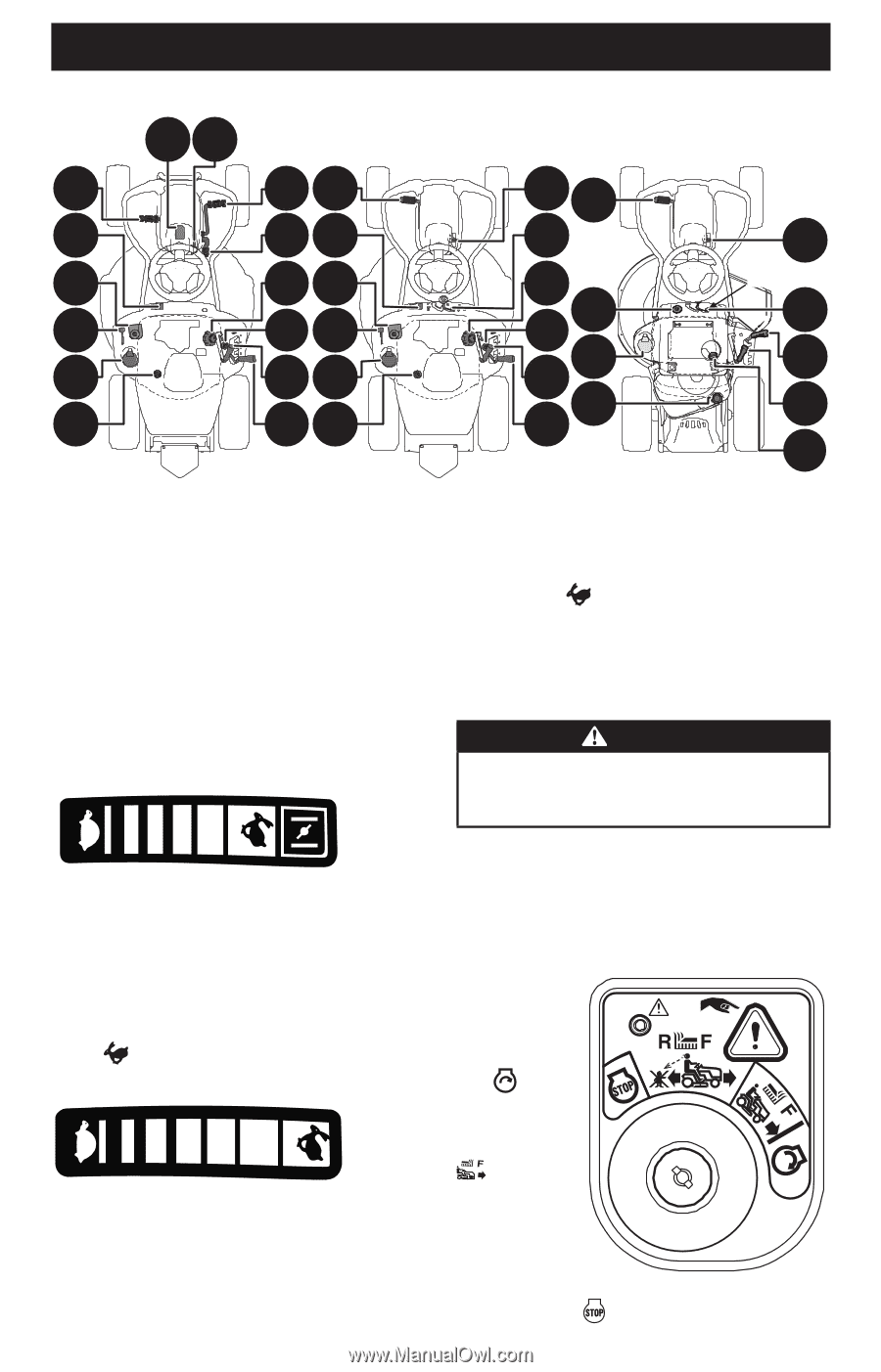
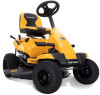
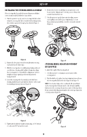
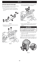
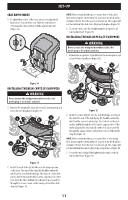
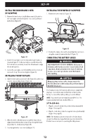
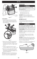
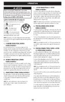
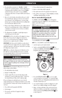
OPERATION Hydro Transmission OG 30" 6-Speed Transmission 24" 6-Speed Transmission E CF HF L DL I H B MB M (I) B I A N* A N* P J P KP K M K N* J N* J N* *--Refer to oil fill cap for location of your oil fill cap. Figure 19 NOTE: This Operator's Manual covers several models. Riding mower features may vary by model. Not all features in this manual are applicable to all riding mower models and the riding mower depicted may differ from yours. Push the throttle control handle forward to increase the engine speed. The riding mower is designed to operate with the throttle control in the FAST position (full throttle) when the mower deck is engaged. NOTE: All references in this manual to the left or right side and front or back of the riding mower are from the operating position only. Exceptions, if any, will be specified. A. THROTTLE/CHOKE CONTROL OR THROTTLE CONTROL LEVER (IF EQUIPPED) Throttle/Choke Control Lever (If equipped) Pull the throttle control handle rearward to decrease the engine speed. B. IGNITION SWITCH MODULE WARNING Never leave a running machine unattended. Always disengage PTO, set parking brake, stop riding mower, and remove the key to prevent unintended starting. FAST SL OW FAST SLOW The throttle/choke control lever is located on the left fender. This lever controls the speed of the engine and, when pushed all the way forward, past the detent position, closes the choke for cold starting. When set in a given position, the throttle will maintain a uniform engine speed. NOTE: When operating the riding mower with the cutting deck engaged, be certain that the throttle/choke control is always in the FAST position. Throttle Control (If equipped) The throttle control is located on the left side of the left fender. When set in a given position, a uniform engine speed will be maintained. The ignition switch module is located on the left fender of the riding mower seated in the operator's position, adjacent to the throttle/choke control or throttle control. Ignition Switch Module with Reverse Caution Mode (If equipped) To start the engine, insert the key into the ignition switch module and turn clockwise to the START position. Release the key into the NORMAL MOWING MODE position once the engine has fired. To stop the engine, turn the ignition key counterclockwise to the STOP position. 14
-
 1
1 -
2
-
3
-
4
-
5
-
6
-
7
-
8
-
 9
9 -
 10
10 -
 11
11 -
 12
12 -
 13
13 -
 14
14 -
 15
15 -
 16
16 -
 17
17 -
 18
18 -
 19
19 -
20
-
21
-
22
-
23
-
24
-
25
-
26
-
27
-
28
-
29
-
30
-
31
-
32
-
33
-
34
-
35
-
36
-
37
-
38
-
39
-
40
-
41
-
42
-
43
-
44
-
45
-
46
-
47
-
48
-
49
-
50
-
51
-
52
-
53
-
54
-
55
-
56
-
57
-
58
-
59
-
60
-
61
-
62
-
63
-
64
-
65
-
66
-
67
-
68
-
69
-
70
-
71
-
72
-
73
-
74
-
75
-
76
-
77
-
78
-
79
-
80
-
81
-
82
-
83
-
84
-
85
-
86
-
87
-
88
-
89
-
90
-
91
-
92
-
93
-
94
-
95
-
96
 |
 |