Cub Cadet CC30H Riding Lawn Mower Operation Manual - Page 16
Shift Lever 6-speed Riding Mowers
 |
View all Cub Cadet CC30H Riding Lawn Mower manuals
Add to My Manuals
Save this manual to your list of manuals |
Page 16 highlights
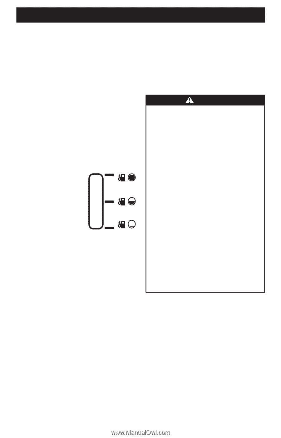
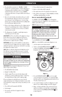
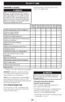
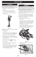
OPERATION I. SHIFT LEVER (6-SPEED RIDING MOWERS) The shift lever is located on the control panel just below the seat, in the center of the riding mower. It has three positions: FORWARD, NEUTRAL and REVERSE. The clutch-brake pedal must be completely depressed and the riding mower must not be in motion when moving the shift lever. J. DECK LIFT LEVER Found on your riding mower's right fender, the deck lift lever is used to change the height of the cutting deck. To use, move the lever to the left, then place in the notch best suited for your application. K. PTO LEVER Found on the riding mower's right fender, the PTO lever is used to engage power to the cutting deck. To operate, move the lever all the way forward. Moving the lever all the way rearward into the OFF position disengages power to the cutting deck. NOTE: The PTO lever must be in the disengaged (OFF) position when starting the engine. L. FUEL LEVER INDICATOR (IF EQUIPPED) The fuel lever indicator is located below the seat on the left hand side from the operator's position in the control panel. Use this window to identify the riding mower's fuel needs. M. FUEL FILL CAP The fuel fill cap is located below the right side of the seat on 30" deck models and on the engine to the rear of the riding mower on 24" deck models. Refer to the Set-up section in this manual for instructions for 30" deck models and the Engine Operator's Manual for 24" deck models for fuel filling instructions. N. OIL FILL CAP The oil fill cap is located under the left side of the seat on models equipped with Briggs & Stratton engines, the oil fill cap is located under the right fender on all other models. Refer to the Engine Operator's Manual for instructions on checking and adding oil to this riding mower. O. HEADLIGHT (IF EQUIPPED) The headlight is ON whenever the key is rotated out of the STOP position. The headlight turns OFF when the ignition key is moved to the STOP position. P. CUP HOLDER The cup holder is located to the left of the operator's seat. TRANSMISSION BYPASS ROD (NOT SHOWN) The transmission bypass rod is located inside the right tire on the lower right section of the frame. When engaged, the rod opens a bypass within the hydrostatic transmission, which allows the riding mower to be pushed short distances by hand. Refer to the Set-up section for instructions on using the bypass feature. OPERATION WARNING Avoid serious injury or death as follows: • Know location and function of all controls. • Remove objects which could be thrown by the blades. • Go up and down slopes, not across. • Use extra caution on slopes. Do not mow slopes greater than 12° (21%). Avoid sudden turns. Use low speed. • Do not operate machine where it could tip or slip. • If machine stops going uphill, stop blades and back down slowly. • Before leaving operator's position, disengage blades, engage parking brake, shut off engine, and remove key. • Be sure blades and engine are stopped before placing hands or feet near blades. • Keep safety devices (guards, shields, switches, etc.) in place and working. • Keep bystanders away. • Allow machine to cool before fueling or storing. • Keep machine free of debris. Read Operator's Manual Safety Interlock Switches This riding mower is equipped with a safety interlock system for the protection of the operator. If the safety interlock system should ever malfunction, do not operate the riding mower. Contact an authorized service dealer. • The safety interlock system prevents the engine from cranking or starting unless the parking brake is engaged and the PTO lever is in the disengaged (OFF) position. • The engine will automatically shut off if the operator leaves the seat before engaging the parking brake. • The engine will automatically shut off if the operator leaves the riding mower's seat with the PTO lever in the engaged (ON) position, regardless of whether the parking brake is engaged. 16
-
 1
1 -
2
-
3
-
4
-
5
-
6
-
7
-
8
-
9
-
10
-
 11
11 -
 12
12 -
 13
13 -
 14
14 -
 15
15 -
 16
16 -
 17
17 -
 18
18 -
 19
19 -
 20
20 -
 21
21 -
22
-
23
-
24
-
25
-
26
-
27
-
28
-
29
-
30
-
31
-
32
-
33
-
34
-
35
-
36
-
37
-
38
-
39
-
40
-
41
-
42
-
43
-
44
-
45
-
46
-
47
-
48
-
49
-
50
-
51
-
52
-
53
-
54
-
55
-
56
-
57
-
58
-
59
-
60
-
61
-
62
-
63
-
64
-
65
-
66
-
67
-
68
-
69
-
70
-
71
-
72
-
73
-
74
-
75
-
76
-
77
-
78
-
79
-
80
-
81
-
82
-
83
-
84
-
85
-
86
-
87
-
88
-
89
-
90
-
91
-
92
-
93
-
94
-
95
-
96
 |
 |