Cub Cadet CC30H Riding Lawn Mower Operation Manual - Page 24
Adjustments
 |
View all Cub Cadet CC30H Riding Lawn Mower manuals
Add to My Manuals
Save this manual to your list of manuals |
Page 24 highlights
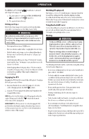
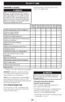
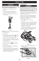
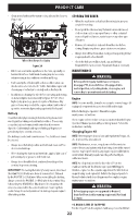
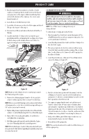
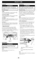
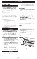
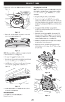
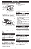
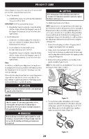
PRODUCT CARE Lubrication WARNING Before lubricating, repairing, or inspecting, always disengage PTO, move shift lever into neutral position, set parking brake, stop engine, and remove key to prevent unintended starting. ENGINE Lubricate the engine with motor oil as instructed in the Engine Operator's Manual packed with your riding mower. PIVOT POINTS & LINKAGE Lubricate all the pivot points on the drive system, parking brake and lift linkage at least once a season with light oil. REAR WHEELS The rear wheels should be removed from the axles once a season. Lubricate the axles and the rims well with an all-purpose grease before re-installing them. FRONT AXLES Each end of the riding mower's front pivot bar may be equipped with a grease fitting. Lubricate with a grease gun after every 25 hours of riding mower operation. STEERING RACK & PINION Once per season or every 25 hours of operation, it will be necessary to lubricate the steering rack and pinion gear (a) located under the front of the riding mower. Using standard automotive grease, apply grease to the front side and rear side of the steering rack and pinion gear (a) (Figure 28). a Parking Brake WARNING Never attempt to adjust the brakes while the engine is running. Always disengage PTO, move shift lever into neutral position, stop engine, and remove key to prevent unintended starting. If the riding mower does not come to a complete stop when the brake pedal is completely depressed or if the riding mower's rear wheels can roll with the parking brake applied, the brake is in need of adjustment. See an authorized service dealer to have brakes properly adjusted. Deck NOTE: Check the riding mower's tire pressure before performing any deck leveling adjustments. Refer to Tire Pressure, in the Set-up section for more information regarding tire pressure. FRONT-TO-REAR LEVELING It is possible to adjust the pitch of the cutting deck. The front of the deck should be between 0" (level) and 1/4" (6 mm) lower than the rear of the deck. Adjust if necessary as follows: 1. With the riding mower parked on a firm, level surface, place the deck lift lever in the middle position and rotate the blade so that it is aligned with the front and rear of the riding mower. 2. Measure the distance from the front of the blade tip to the ground and the rear of the blade tip to the ground. The first measurement taken should be between 0" (level) and 1/4" (6 mm) less than the second measurement. Determine the approximate distance necessary for proper adjustment and proceed, if necessary, to the next step. 3. Locate the flange lock nut (a) on the front end of the PTO lift rod (b) (Figure 29). Figure 28 ADJUSTMENTS WARNING Never attempt to make any adjustments while the engine is running, except where specified in the Operator's Manual. Seat Refer to the Set-up section of this manual for seat adjustment instructions. b a Figure 29 • Tighten the flange lock nut (a) to raise the front of the deck. • Loosen the flange lock nut (a) to lower the front of the deck. Tires Refer to Tire Pressure, in the Set-up section for more information regarding tire pressure. 24
-
 1
1 -
2
-
3
-
4
-
5
-
6
-
7
-
8
-
9
-
10
-
11
-
12
-
13
-
14
-
15
-
16
-
17
-
18
-
 19
19 -
 20
20 -
 21
21 -
 22
22 -
 23
23 -
 24
24 -
 25
25 -
 26
26 -
 27
27 -
 28
28 -
 29
29 -
30
-
31
-
32
-
33
-
34
-
35
-
36
-
37
-
38
-
39
-
40
-
41
-
42
-
43
-
44
-
45
-
46
-
47
-
48
-
49
-
50
-
51
-
52
-
53
-
54
-
55
-
56
-
57
-
58
-
59
-
60
-
61
-
62
-
63
-
64
-
65
-
66
-
67
-
68
-
69
-
70
-
71
-
72
-
73
-
74
-
75
-
76
-
77
-
78
-
79
-
80
-
81
-
82
-
83
-
84
-
85
-
86
-
87
-
88
-
89
-
90
-
91
-
92
-
93
-
94
-
95
-
96
 |
 |
