Cub Cadet CC30H Riding Lawn Mower Operation Manual - Page 12
Warning, Caution
 |
View all Cub Cadet CC30H Riding Lawn Mower manuals
Add to My Manuals
Save this manual to your list of manuals |
Page 12 highlights
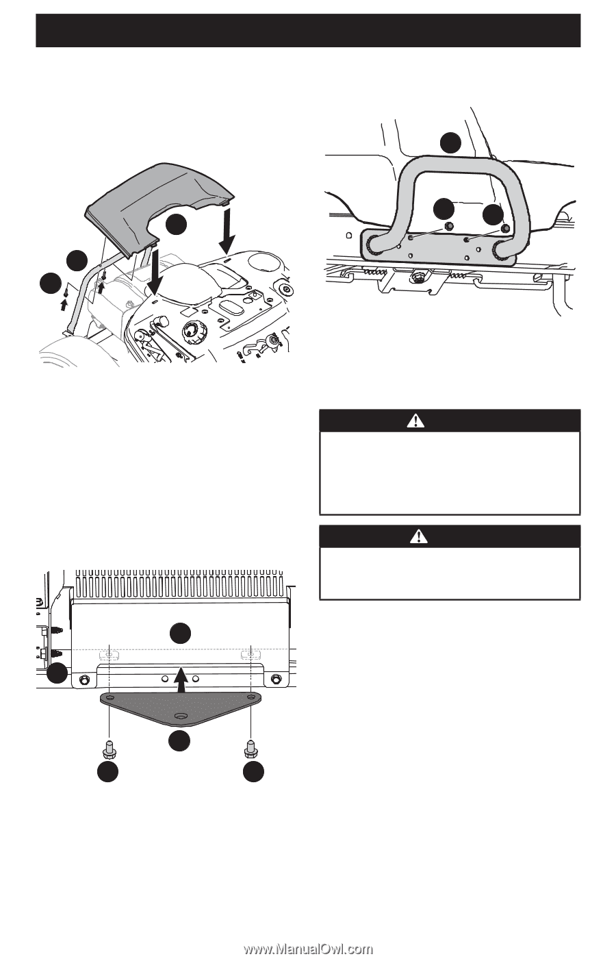
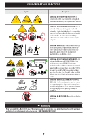
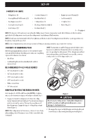
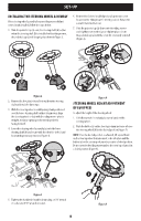
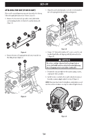
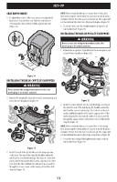
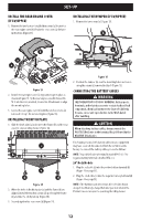
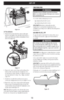
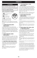
SET-UP INSTALL THE REAR ENGINE COVER (IF EQUIPPED) 1. Remove the two factory-installed hex screws (a) located on the rear engine cover (b). Retain the hex screws (a) for later instructions (Figure 13). INSTALLING THE BUMPER (IF EQUIPPED) 1. Remove the two screws (a) (Figure 15). b b a a a a Figure 13 2. Install the rear engine cover (b) by positioning it in place as shown in Figure 13. Tip the rear engine cover (b) forward to fit it into the slots provided, then rotate it backwards to align the mounting holes. 3. Secure the rear engine cover (b) with the two hex screws (a) removed in Step 1. Do not over-tighten (Figure 13). INSTALLING THE HITCH PLATE 1. Slide the hitch plate (a) in between the frame (b) and the rear cover (c) on your riding mower (Figure 14). c b a (dd) d Figure 14 2. When the holes in the hitch plate (a) and the frame (b) are aligned, install the two hex screws (d) up through the frame (b) and into the hitch plate (a) (Figure 14). 3. Securely tighten the hex screws (d) (Figure 14). Figure 15 2. Position the bumper (b) over the mounting holes and secure using the screws (a) removed in Step 1 (Figure 15). CONNECTING THE BATTERY CABLES WARNING CALIFORNIA PROPOSITION 65 WARNING: Battery posts, terminals, and related accessories contain lead and lead compounds, chemicals known to the State of California to cause cancer and reproductive harm. Wash hands after handling. CAUTION When attaching battery cables, always connect the POSITIVE (Red) wire to the terminal first, followed by the NEGATIVE (Black) wire. For shipping reasons, both battery cables on your equipment may have been left disconnected from the terminals at the factory. To connect the battery cables, proceed as follows: NOTE: The positive battery terminal is marked POS. (+). The negative battery terminal is marked NEG. (-). 24" Deck Models 1. Plug the red cable (a) into the positive battery terminal (b) (Figure 16 on page 13). 2. Plug the black cable (c) into the negative battery terminal (d) (Figure 16 on page 13). NOTE: If the battery is put into service after the date shown on top/side of battery, charge the battery as instructed in the Product Care section prior to operating the riding mower. 12
-
 1
1 -
2
-
3
-
4
-
5
-
6
-
 7
7 -
 8
8 -
 9
9 -
 10
10 -
 11
11 -
 12
12 -
 13
13 -
 14
14 -
 15
15 -
 16
16 -
 17
17 -
18
-
19
-
20
-
21
-
22
-
23
-
24
-
25
-
26
-
27
-
28
-
29
-
30
-
31
-
32
-
33
-
34
-
35
-
36
-
37
-
38
-
39
-
40
-
41
-
42
-
43
-
44
-
45
-
46
-
47
-
48
-
49
-
50
-
51
-
52
-
53
-
54
-
55
-
56
-
57
-
58
-
59
-
60
-
61
-
62
-
63
-
64
-
65
-
66
-
67
-
68
-
69
-
70
-
71
-
72
-
73
-
74
-
75
-
76
-
77
-
78
-
79
-
80
-
81
-
82
-
83
-
84
-
85
-
86
-
87
-
88
-
89
-
90
-
91
-
92
-
93
-
94
-
95
-
96
 |
 |