Cub Cadet CC30H Riding Lawn Mower Operation Manual - Page 8
SET-UP
 |
View all Cub Cadet CC30H Riding Lawn Mower manuals
Add to My Manuals
Save this manual to your list of manuals |
Page 8 highlights
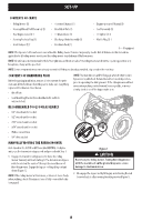
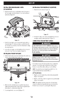
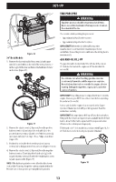
SET-UP CONTENTS OF CRATE • Riding Mower (1) • Operator's Manual (1) • Engine Operator's Manual (1) • Steering Wheel/Shaft Assembly (1) • Rear Hitch Plate (1) • Seat Assembly (1) • Rear Engine Cover (1) † • Oil Drain Sleeve (1) • Oil Siphon (1) † • Steering Pedestal Cap (1) • Discharge Chute Assembly (1) • Mulch Plug (1) † • Front Bumper (1) † • Hardware Pack (1) † - If equipped NOTE: This Operator's Manual covers several models. Riding mower features may vary by model. Not all features in this manual are applicable to all riding mower models and the riding mower depicted may differ from yours. NOTE: All references in this manual to the left or right side and front or back of the riding mower are from the operating position only. Exceptions, if any, will be specified. NOTE: Some components may come already assembled. If they are already assembled, skip ahead to the next step. CONTENTS OF HARDWARE PACK Before beginning installation, remove all the contents from the crate and all the hardware from the pack to make sure everything is present. Hardware is listed below. • Hitch Plate • Seat Mounting Bracket (two shoulder bolts and lock nuts installed) NOTE: The transmission will NOT engage when the hydrostatic bypass rod is pulled out. Return the rod to its normal position prior to operating the riding mower. If the riding mower will not move when pushing on the forward/reverse pedals, or moves slowly, check to see if the bypass valve is on. RECOMMENDED TOOLS FOR ASSEMBLY • 3/8" wrench and/or socket • 1/2" wrench and/or socket • 7/16" wrench and/or socket • 9/16" wrench and/or socket • Phillips screw driver • 1/4" drive ratchet MANUALLY MOVING THE RIDING MOWER On 6-Speed units, shift the shift lever into NEUTRAL. On Hydro units, use the transmission bypass rod and proceed with Step 1. 1. Engage the transmission bypass rod to move the riding mower manually without starting it. The transmission bypass rod is located on the inside of the right tire near the rear of the riding mower. Engage the bypass rod by pulling out and down (Figure 1). NOTE: If the riding mower will not move, or does not move freely when pushing, check if the bypass lever is fully open or the brake is engaged. Figure 1 CAUTION Never tow your riding mower. Towing the riding mower with the rear wheels on the ground may cause severe damage to the transmission. 2. Disengage the bypass rod by lifting up and allowing the rod to move back in after moving the riding mower (Figure 1). 8
-
 1
1 -
2
-
 3
3 -
 4
4 -
 5
5 -
 6
6 -
 7
7 -
 8
8 -
 9
9 -
 10
10 -
 11
11 -
 12
12 -
 13
13 -
14
-
15
-
16
-
17
-
18
-
19
-
20
-
21
-
22
-
23
-
24
-
25
-
26
-
27
-
28
-
29
-
30
-
31
-
32
-
33
-
34
-
35
-
36
-
37
-
38
-
39
-
40
-
41
-
42
-
43
-
44
-
45
-
46
-
47
-
48
-
49
-
50
-
51
-
52
-
53
-
54
-
55
-
56
-
57
-
58
-
59
-
60
-
61
-
62
-
63
-
64
-
65
-
66
-
67
-
68
-
69
-
70
-
71
-
72
-
73
-
74
-
75
-
76
-
77
-
78
-
79
-
80
-
81
-
82
-
83
-
84
-
85
-
86
-
87
-
88
-
89
-
90
-
91
-
92
-
93
-
94
-
95
-
96
 |
 |