Cub Cadet CC30H Riding Lawn Mower Operation Manual - Page 9
Installing The Steering Wheel Assembly, Steering Wheel Height Adjustment, If Equipped
 |
View all Cub Cadet CC30H Riding Lawn Mower manuals
Add to My Manuals
Save this manual to your list of manuals |
Page 9 highlights
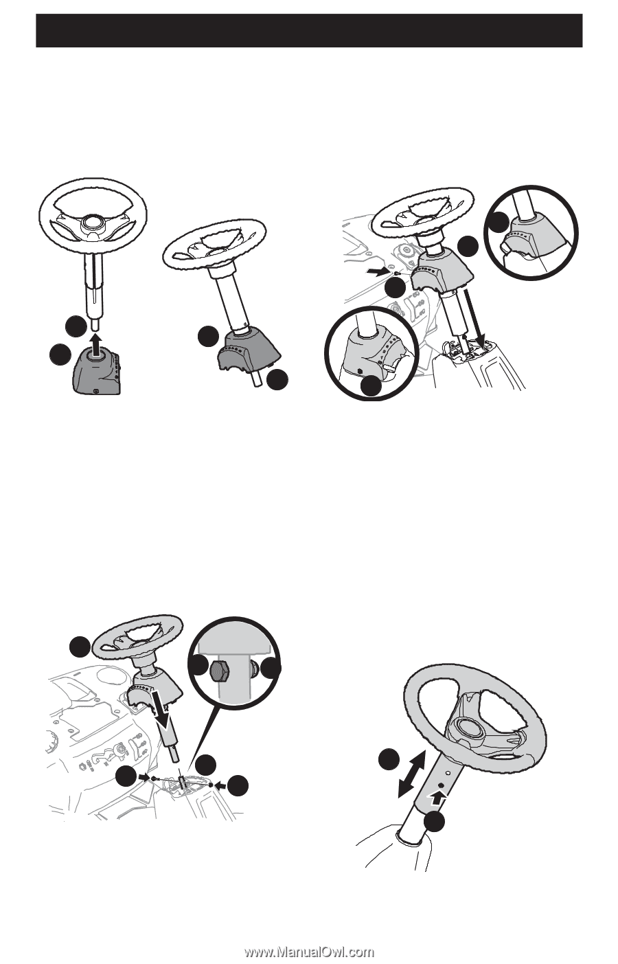
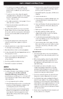
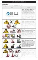
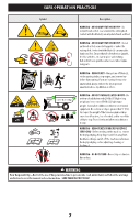
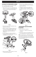
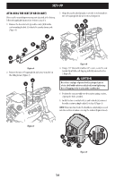
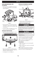
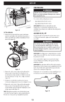
SET-UP INSTALLING THE STEERING WHEEL ASSEMBLY If the steering wheel assembly for your riding mower did not come already installed, follow the steps below: 1. Slide the pedestal cap (a) onto the steering shaft (b) so that when the steering shaft (b) is installed on the riding mower, the pedestal cap (a) will be upright as shown in Figure 2. 6. Remove the factory-installed pedestal cap mount screw located on the riding mower's steering console. Retain the screw for later instructions. 7. Slide the pedestal cap (a) down onto the riding mower and slightly rotate to the right to clip into place. Secure the pedestal cap (a) with the screw (b) previously removed (Figure 4). b a a b Figure 2 2. Remove the shoulder bolt and lock nut from the steering shaft and retain for later steps. 3. With the steering wheel assembly upright and positioned over the lower steering shaft on the riding mower, align the steering wheel so that with the riding mower wheels straight, the large opening on the steering wheel is facing forward. 4. Lower the steering wheel assembly (a) onto the lower steering shaft (b) and secure with the shoulder bolt (c) and lock nut (d) previously removed (Figure 3). a c d a a b a Figure 4 STEERING WHEEL HEIGHT ADJUSTMENT (IF EQUIPPED) To adjust the height of the steering wheel: 1. Sit in the operator's seat and place your hands on the steering wheel. 2. Push the button (a) on the steering column and raise or lower the steering wheel (b) to the desired position (Figure 5). NOTE: Once the desired position is achieved, lift up and down on the steering wheel to make sure it locks into place and the button (a) on the steering column releases into a locked position. Do not operate the riding mower unless the steering column is in a locked position (Figure 5). b c d Figure 3 5. Tighten the shoulder bolt and lock nut using a 9/16" wrench or socket and 7/16" wrench or socket. 9 b a Figure 5
-
 1
1 -
2
-
3
-
 4
4 -
 5
5 -
 6
6 -
 7
7 -
 8
8 -
 9
9 -
 10
10 -
 11
11 -
 12
12 -
 13
13 -
 14
14 -
15
-
16
-
17
-
18
-
19
-
20
-
21
-
22
-
23
-
24
-
25
-
26
-
27
-
28
-
29
-
30
-
31
-
32
-
33
-
34
-
35
-
36
-
37
-
38
-
39
-
40
-
41
-
42
-
43
-
44
-
45
-
46
-
47
-
48
-
49
-
50
-
51
-
52
-
53
-
54
-
55
-
56
-
57
-
58
-
59
-
60
-
61
-
62
-
63
-
64
-
65
-
66
-
67
-
68
-
69
-
70
-
71
-
72
-
73
-
74
-
75
-
76
-
77
-
78
-
79
-
80
-
81
-
82
-
83
-
84
-
85
-
86
-
87
-
88
-
89
-
90
-
91
-
92
-
93
-
94
-
95
-
96
 |
 |