Dell Dimension 2010 Service Manual - Page 52
Rotate the processor fan and heat sink assembly upward gently,
 |
View all Dell Dimension 2010 manuals
Add to My Manuals
Save this manual to your list of manuals |
Page 52 highlights
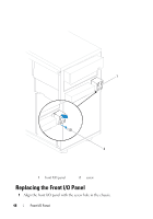
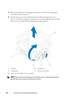
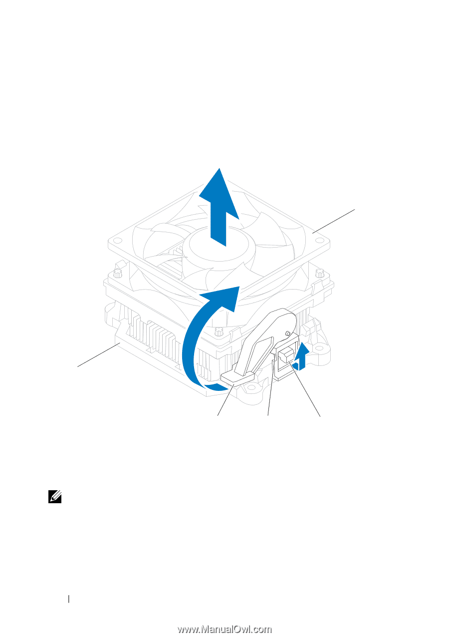
5 Rotate the clamp lever 180 degrees clockwise to release the clamp grip from the bracket projection. 6 Rotate the processor fan and heat sink assembly upward gently, and remove it from the computer. Lay the processor fan and heat sink assembly down on its top, with the thermal grease facing upward. 5 1 2 3 4 1 bracket 2 clamp lever 3 clamp grip 4 bracket projection 5 processor fan and heat sink assembly NOTE: The processor fan and heat sink assembly in your computer may not look exactly like the one shown in the illustration above. 52 Processor Fan and Heat Sink Assembly
-
 1
1 -
2
-
3
-
4
-
5
-
6
-
7
-
8
-
9
-
10
-
11
-
12
-
13
-
14
-
15
-
16
-
17
-
18
-
19
-
20
-
21
-
22
-
23
-
24
-
25
-
26
-
27
-
28
-
29
-
30
-
31
-
32
-
33
-
34
-
35
-
36
-
37
-
38
-
39
-
40
-
41
-
42
-
43
-
44
-
45
-
46
-
 47
47 -
 48
48 -
 49
49 -
 50
50 -
 51
51 -
 52
52 -
 53
53 -
 54
54 -
 55
55 -
 56
56 -
 57
57 -
58
-
59
-
60
-
61
-
62
-
63
-
64
-
65
-
66
-
67
-
68
-
69
-
70
-
71
-
72
-
73
-
74
-
75
-
76
-
77
-
78
 |
 |
52
Processor Fan and Heat Sink Assembly
5
Rotate the clamp lever 180 degrees clockwise to release the clamp grip
from the bracket projection.
6
Rotate the processor fan and heat sink assembly upward gently, and
remove it from the computer. Lay the processor fan and heat sink assembly
down on its top, with the thermal grease facing upward.
NOTE:
The processor fan and heat sink assembly in your computer may not look
exactly like the one shown in the illustration above.
1
bracket
2
clamp lever
3
clamp grip
4
bracket projection
5
processor fan and heat sink assembly
3
4
2
5
1