Dell Equallogic PS4110X PS4110 Hardware Owners Manual
Dell Equallogic PS4110X Manual
 |
View all Dell Equallogic PS4110X manuals
Add to My Manuals
Save this manual to your list of manuals |
Dell Equallogic PS4110X manual content summary:
- Dell Equallogic PS4110X | PS4110 Hardware Owners Manual - Page 1
PS4110 Storage Arrays Hardware Owner's Manual Version 1.0 - Dell Equallogic PS4110X | PS4110 Hardware Owners Manual - Page 2
Copyright 2011-2013 Dell Inc. All rights reserved. Dell and EqualLogic are trademarks of Dell Inc. All trademarks and registered trademarks mentioned herein are the property of their respective owners. Information in this document is subject to change without notice. - Dell Equallogic PS4110X | PS4110 Hardware Owners Manual - Page 3
Support and Customer Service 39 Determining Service Tag Information 40 Obtaining Component Diagnostics 40 Troubleshooting Array Startup Failure 40 Troubleshooting Loss of Communication 40 Troubleshooting Array Connections 40 Troubleshooting External Connections 41 Troubleshooting - Dell Equallogic PS4110X | PS4110 Hardware Owners Manual - Page 4
- Dell Equallogic PS4110X | PS4110 Hardware Owners Manual - Page 5
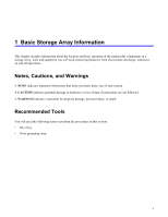
important information that helps you make better use of your system. A CAUTION indicates potential damage to hardware or loss of data if instructions are not followed. A WARNING indicates a potential for property damage, personal injury, or death. Recommended Tools You will need the following items - Dell Equallogic PS4110X | PS4110 Hardware Owners Manual - Page 6
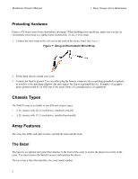
Hardware Owner's Manual 1 Basic Storage Array Information Protecting Hardware Protect a PS Series array from electrostatic discharge. When handling array hardware, make sure you use an electrostatic wrist strap - Dell Equallogic PS4110X | PS4110 Hardware Owners Manual - Page 7
Hardware Owner's Manual 1 Basic Storage Array Information Removing the Bezel The steps for removing the bezel are the same for all array models. 1. Using the bezel key, unlock - Dell Equallogic PS4110X | PS4110 Hardware Owners Manual - Page 8
Hardware Owner's Manual 1 Basic Storage Array Information Table 1 describes the front panel features a built-in chassis control panel that is not hot-swappable and can be replaced only by support personnel. During the array power-up sequence, these LEDs will cycle through different states until the - Dell Equallogic PS4110X | PS4110 Hardware Owners Manual - Page 9
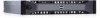
Hardware Owner's Manual 1 Basic Storage Array Information Back-Panel Features and Indicators The back of a PS4110 is shown in Figure 5. Table 2 describes the back panel features. Figure 5: Back - Dell Equallogic PS4110X | PS4110 Hardware Owners Manual - Page 10
Hardware Owner's Manual 1 Basic Storage Array Information • Use telnet or SSH to connect Enter the shutdown command, as shown next. login: grpadmin Password: Welcome to Group Manager Copyright 2001-2011 Dell, Inc. group1> shutdown If you are using a serial connection to shut down an array, it is - Dell Equallogic PS4110X | PS4110 Hardware Owners Manual - Page 11
supports up to 24 2.5-inch SAS drives or up to 12 3.5-inch SAS drives in internal drive bays. Drives are connected to a backplane through drive carriers and are hot-swappable. Drives are supplied in a carrier that is keyed to fit into specific array models, and cannot be installed in other Dell - Dell Equallogic PS4110X | PS4110 Hardware Owners Manual - Page 12
Hardware Owner's Manual 2 Maintaining Drives Interpreting Drive LEDs The LEDs on a 3.5-inch drive are shown in Figure 6. The LEDs on a 2.5-inch drive are shown in Figure 7. Drive LED - Dell Equallogic PS4110X | PS4110 Hardware Owners Manual - Page 13
Hardware Owner's Manual 2 Maintaining Drives Array Behavior When a Drive Fails How an a drive assembly or a blank car- rier. Operating an array with an empty slot will void your warranty and support contract. • Do not remove a functioning drive (other than a spare) from an array. If the drive is - Dell Equallogic PS4110X | PS4110 Hardware Owners Manual - Page 14
Hardware Owner's Manual 2 Maintaining Drives Drive Installation Guidelines and Restrictions • Replace a failed drive as soon as possible to provide the highest availability. • Install only drives of the same - Dell Equallogic PS4110X | PS4110 Hardware Owners Manual - Page 15
Hardware Owner's Manual Figure 8: Removing a 2.5-Inch Drive 2 Maintaining Drives Installing a 2.5-inch Drive The 2.5-inch drives are installed vertically, with the drive release latch on the top and the - Dell Equallogic PS4110X | PS4110 Hardware Owners Manual - Page 16
Hardware Owner's Manual 2 Maintaining Drives 4. Push the drive completely into the slot (callout 2). The drive handle will begin to close onto the drive (callout 3). 5. Push in the handle - Dell Equallogic PS4110X | PS4110 Hardware Owners Manual - Page 17
Hardware Owner's Manual 2 Maintaining Drives 2. Press the release button (callout 1 in Figure 10). The drive latch opens and the drive emerges partway from the array (callout 2). 3. Pull the - Dell Equallogic PS4110X | PS4110 Hardware Owners Manual - Page 18
Hardware Owner's Manual 2 Maintaining Drives 3. Hold the drive by the carrier and slide the drive most of the way into a slot (callout 1 in Figure 11). 4. Push the drive - Dell Equallogic PS4110X | PS4110 Hardware Owners Manual - Page 19
Hardware Owner's Manual 2 Maintaining Drives 1. Remove the bezel. See Removing the Bezel on page 3. 2. Press the release tab and slide the drive blank out until it is free - Dell Equallogic PS4110X | PS4110 Hardware Owners Manual - Page 20
- Dell Equallogic PS4110X | PS4110 Hardware Owners Manual - Page 21
, control module pair, and drives determines the PS Series array model number. The control modules in a PS Series array contain the PS Series firmware which provides the Group Manager GUI, the command line interface, and all the array and storage management functions and features. Ideally, an array - Dell Equallogic PS4110X | PS4110 Hardware Owners Manual - Page 22
Manual Release Notes for information about other supported control modules. About Control Module Configurations all the volumes on it) becomes unavailable. Dell strongly recommends buying an array with two control takes over immediately with no interruption of service. This gives you time to replace - Dell Equallogic PS4110X | PS4110 Hardware Owners Manual - Page 23
Hardware Owner's Manual 3 Maintaining Control Modules Figure 14: Recommended Network Configuration to Support Vertical Failover Note: If a network port is available for failover on either control module, but is not currently in use, its LEDs will not be - Dell Equallogic PS4110X | PS4110 Hardware Owners Manual - Page 24
Hardware Owner's Manual 3 Maintaining Control Modules Table 5: Ethernet and Management Port LED Descriptions 10GBASE-T Ethernet LED Location State Description Left (Link) Off No power, not connected to network, - Dell Equallogic PS4110X | PS4110 Hardware Owners Manual - Page 25
Owner's Manual 3 on page 3. If a control module fails, contact your PS Series support provider for a replacement. Understanding Failover Behavior In a dual control module Module Firmware A control module has a microSD card running the array firmware. You should run the latest firmware version - Dell Equallogic PS4110X | PS4110 Hardware Owners Manual - Page 26
second control module, upgrading a control module, or replacing a failed microSD card, contact your PS Series support provider for a replacement. Inform your provider of the current PS Series firmware version on your system. If you are replacing a failed control module, remove the microSD card from - Dell Equallogic PS4110X | PS4110 Hardware Owners Manual - Page 27
Hardware Owner's Manual 3 Maintaining Control Modules Figure 16: Standby Button Location Enabling the Standby Feature To use the standby button, a group administrator must enable the feature in the - Dell Equallogic PS4110X | PS4110 Hardware Owners Manual - Page 28
Manual activity to or from the member, and the member's firmware is not running. Use the Standby On/Off button only GUI or CLI; for example, if you discover a problem in your lab environment, such as high temperature or a service provider. • Do not remove a failed control module until you are - Dell Equallogic PS4110X | PS4110 Hardware Owners Manual - Page 29
Hardware Owner's Manual 3 Maintaining Control Modules Control Module Replacement Procedures This section describes the procedures for removing and replacing one or both control modules in your PS Series - Dell Equallogic PS4110X | PS4110 Hardware Owners Manual - Page 30
Hardware Owner's Manual 3 Maintaining Control Modules 3. Replace the control module that is now Secondary Control Module on page 25.) Removing a Control Module Before removing a control module: • Review the information at the beginning of Replacing a Control Module on page 24. • Attach an - Dell Equallogic PS4110X | PS4110 Hardware Owners Manual - Page 31
Hardware Owner's Manual 3 Maintaining will make sure that the new control module is running the correct firmware. See Replacing the MicroSD Card on page 29. Caution: Do replacement module was shipped. Contact your PS Series support provider for information about returning hardware. Installing a - Dell Equallogic PS4110X | PS4110 Hardware Owners Manual - Page 32
Hardware Owner's Manual 3 Maintaining Control Modules Figure 18: Correct Control Module Orientation To install a control module: 1. Attach an electrostatic wrist strap, or similar protective device. See "Protecting Hardware " - Dell Equallogic PS4110X | PS4110 Hardware Owners Manual - Page 33
's Manual ), contact your support provider. Replacing the MicroSD Card Each control module includes a microSD card that contains the PS Series firmware. If a control same firmware as the other control module in the array. Before you begin the procedure to replace a microSD card: • Review Replacing - Dell Equallogic PS4110X | PS4110 Hardware Owners Manual - Page 34
Hardware Owner's Manual 3 Maintaining Control Modules 1. Firmly push the card into its housing to release the spring mechanism (callout 2 in Figure 20). The microSD card will be partially - Dell Equallogic PS4110X | PS4110 Hardware Owners Manual - Page 35
Hardware Owner's Manual 3 Maintaining Control Modules Figure 21: Inserting the MicroSD Card 3. Install the control module in the array. See Installing a Control Module on page 27. 4. Make sure - Dell Equallogic PS4110X | PS4110 Hardware Owners Manual - Page 36
Manual 3 Maintaining Control Modules Note: This is considered an advanced configuration, available if your environment requires this level of security. Hardware Steps 1. Make sure your network environment can support Series Group Administration guide for the procedure to configure the management network in - Dell Equallogic PS4110X | PS4110 Hardware Owners Manual - Page 37
4 Maintaining Power Supply and Cooling Modules The array can support two hot-swappable power supply and cooling modules. The array can operate only temporarily with one module, but both modules must be present for long- - Dell Equallogic PS4110X | PS4110 Hardware Owners Manual - Page 38
Blinks briefly when power is first turned on to the power supply module. For a list of warning or critical level faults, see the Group Administration manual. ON-Power supply module is connected to a source of AC power whether or not the 3 AC power Green power switch is on. OFF-Power supply - Dell Equallogic PS4110X | PS4110 Hardware Owners Manual - Page 39
Hardware Owner's Manual 4 Maintaining Power Supply and Cooling Modules Removing a Power Supply and Cooling Module If a power supply and cooling module fails thumb. 5. Pull the module from the slot, as shown in the following illustration. Caution: The module is heavy; support it with two hands. 35 - Dell Equallogic PS4110X | PS4110 Hardware Owners Manual - Page 40
Hardware Owner's Manual 4 Maintaining Power Supply and Cooling Modules Figure 24: Removing a Power Supply and Cooling Module Installing a Power Supply and Cooling Module To install a power supply and - Dell Equallogic PS4110X | PS4110 Hardware Owners Manual - Page 41
Hardware Owner's Manual 4 Maintaining Power Supply and Cooling Modules Figure 25: Inserting a Power Supply and Cooling Module 3. Make sure the power switch is in the OFF position. 4. Connect - Dell Equallogic PS4110X | PS4110 Hardware Owners Manual - Page 42
Hardware Owner's Manual 4 Maintaining Power Supply and Cooling Modules Figure 26: Securing the Power Cables 38 - Dell Equallogic PS4110X | PS4110 Hardware Owners Manual - Page 43
only perform troubleshooting and simple repairs as authorized in your product documentation, or as directed by the online or telephone service and support team. Damage due to servicing that is not authorized by Dell is not covered by your warranty. Read and follow the safety instructions that came - Dell Equallogic PS4110X | PS4110 Hardware Owners Manual - Page 44
Manual 5 Troubleshooting Your Array Determining Service Tag Information Each array has a service tag with a number. You may need to provide this information to customer support when you contact us. • The service Administration guide or the CLI Reference for more information. Troubleshooting Array - Dell Equallogic PS4110X | PS4110 Hardware Owners Manual - Page 45
Support and Customer Service on page 39. Troubleshooting Array Cooling Problems Check for and correct any of the following situations: • Empty drive bays (no drive or drive blank). • Ambient temperature is too high. See the Technical Specifications for the array in the Installation and Setup Guide - Dell Equallogic PS4110X | PS4110 Hardware Owners Manual - Page 46
Owner's Manual 5 Troubleshooting Your Array • External airflow is obstructed. • The power supply and cooling module is removed or has failed. See Troubleshooting Power Supply and Cool- ing Modules on page 41. If the problem is not resolved, see Obtaining Technical Support and Customer Service on - Dell Equallogic PS4110X | PS4110 Hardware Owners Manual - Page 47
checking proper installation failover behavior failure indications features firmware requirements firmware version handling requirements installing in array LEDs locating removing from array restriction on mixing restrictions supported disk type synchronizing types verifying operational status - Dell Equallogic PS4110X | PS4110 Hardware Owners Manual - Page 48
recommended tools removing 3.5-inch drive drive blank requirements control modules cooling disks firmware power S safety shutting down an array status control modules T troubleshooting connections cooling problems external connections hard drives loss of communication power supply/cooling fan module
-
 1
1 -
 2
2 -
 3
3 -
 4
4 -
 5
5 -
 6
6 -
 7
7 -
8
-
9
-
10
-
11
-
12
-
13
-
14
-
15
-
16
-
17
-
18
-
19
-
20
-
21
-
22
-
23
-
24
-
25
-
26
-
27
-
28
-
29
-
30
-
31
-
32
-
33
-
34
-
35
-
36
-
37
-
38
-
39
-
40
-
41
-
42
-
43
-
44
-
45
-
46
-
47
-
48
 |
 |

PS4110 Storage Arrays
Hardware Owner's Manual
Version 1.0