Dell Equallogic PS4110X PS4110 Hardware Owners Manual - Page 32
Correct Control Module Orientation, Installing a Control Module 2U Array
 |
View all Dell Equallogic PS4110X manuals
Add to My Manuals
Save this manual to your list of manuals |
Page 32 highlights
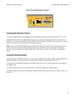
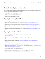
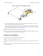
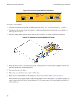
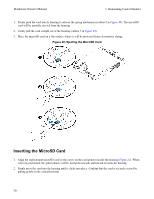
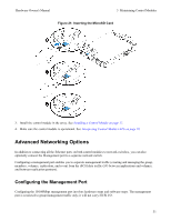
Hardware Owner's Manual 3 Maintaining Control Modules Figure 18: Correct Control Module Orientation To install a control module: 1. Attach an electrostatic wrist strap, or similar protective device. See "Protecting Hardware " on page 2. 2. Push down on the orange release tab (callout 1 in following illustration) and swing the lever (callout 2 in following illustration) out. 3. Slide the control module into the chassis until you feel resistance, as shown in following illustration. Figure 19: Installing a Control Module (2U Array) 4. Rotate the lever (callout 2 in illustration) inward, which pushes the control module completely into the slot. The latch on the lever will snap into place. 5. Reconnect the network cables. 6. If the array was shut down, turn on power to the array. 7. Make sure the control module is operational. See Interpreting Control Module LEDs on page 19. When connected, the control module cache-to-flash module receives full charge. If it cannot be charged, its status is reported as BAD in the Group Manager GUI. You must remove the control module and replace it with another one. 28
-
 1
1 -
2
-
3
-
4
-
5
-
6
-
7
-
8
-
9
-
10
-
11
-
12
-
13
-
14
-
15
-
16
-
17
-
18
-
19
-
20
-
21
-
22
-
23
-
24
-
25
-
26
-
 27
27 -
 28
28 -
 29
29 -
 30
30 -
 31
31 -
 32
32 -
 33
33 -
 34
34 -
 35
35 -
 36
36 -
 37
37 -
38
-
39
-
40
-
41
-
42
-
43
-
44
-
45
-
46
-
47
-
48
 |
 |
