Dell Equallogic PS4110X PS4110 Hardware Owners Manual - Page 23
Interpreting Control Module LEDs
 |
View all Dell Equallogic PS4110X manuals
Add to My Manuals
Save this manual to your list of manuals |
Page 23 highlights
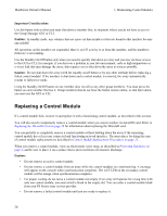
Hardware Owner's Manual 3 Maintaining Control Modules Figure 14: Recommended Network Configuration to Support Vertical Failover Note: If a network port is available for failover on either control module, but is not currently in use, its LEDs will not be lit. Interpreting Control Module LEDs Control modules have the following LEDs: • The Ethernet ports and the Management port each have LEDs that indicate the port's status and activity. • Below the release latch is a column of three LEDs that indicate the status of the entire control module. Figure 15: Control Module LEDs 19
-
 1
1 -
2
-
3
-
4
-
5
-
6
-
7
-
8
-
9
-
10
-
11
-
12
-
13
-
14
-
15
-
16
-
17
-
 18
18 -
 19
19 -
 20
20 -
 21
21 -
 22
22 -
 23
23 -
 24
24 -
 25
25 -
 26
26 -
 27
27 -
 28
28 -
29
-
30
-
31
-
32
-
33
-
34
-
35
-
36
-
37
-
38
-
39
-
40
-
41
-
42
-
43
-
44
-
45
-
46
-
47
-
48
 |
 |

Hardware Owner's Manual
3 Maintaining Control Modules
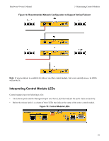
Figure 14: Recommended Network Configuration to Support Vertical Failover
Note:
If a network port is available for failover on either control module, but is not currently in use, its LEDs
will not be lit.
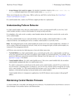
Interpreting Control Module LEDs
Control modules have the following LEDs:
•
The Ethernet ports and the Management port each have LEDs that indicate the port's status and activity.
•
Below the release latch is a column of three LEDs that indicate the status of the entire control module.
Figure 15: Control Module LEDs
19