Dell Equallogic PS4110X PS4110 Hardware Owners Manual - Page 38
W Power Supply LEDs, Table 7: Power Supply LED Descriptions, Group Administration
 |
View all Dell Equallogic PS4110X manuals
Add to My Manuals
Save this manual to your list of manuals |
Page 38 highlights
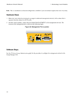
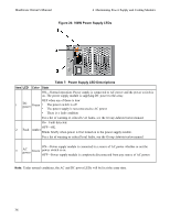
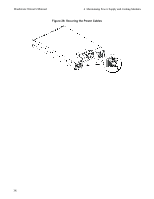
Hardware Owner's Manual 4 Maintaining Power Supply and Cooling Modules Figure 23: 700W Power Supply LEDs Table 7: Power Supply LED Descriptions Item LED Color State ON-Normal operation. Power supply is connected to AC power and the power switch is on. The power supply module is supplying DC power to the array. OFF when any of these is true: 1 DC power Green • The power switch is off • The power supply is not connected to AC power • There is a fault condition For a list of warning or critical level faults, see the Group Administration manual. On-Fault detected. OFF-OK. 2 Fault Amber Blinks briefly when power is first turned on to the power supply module. For a list of warning or critical level faults, see the Group Administration manual. ON-Power supply module is connected to a source of AC power whether or not the 3 AC power Green power switch is on. OFF-Power supply module is completely disconnected from any source of AC power. Note: Under normal conditions, the AC and DC power LEDs will be lit at the same time. 34
-
 1
1 -
2
-
3
-
4
-
5
-
6
-
7
-
8
-
9
-
10
-
11
-
12
-
13
-
14
-
15
-
16
-
17
-
18
-
19
-
20
-
21
-
22
-
23
-
24
-
25
-
26
-
27
-
28
-
29
-
30
-
31
-
32
-
 33
33 -
 34
34 -
 35
35 -
 36
36 -
 37
37 -
 38
38 -
 39
39 -
 40
40 -
 41
41 -
 42
42 -
 43
43 -
44
-
45
-
46
-
47
-
48
 |
 |
