Dell Equallogic PS4110X PS4110 Hardware Owners Manual - Page 24
Identifying Control Module Failures, Table 5: Ethernet and Management Port LED Descriptions
 |
View all Dell Equallogic PS4110X manuals
Add to My Manuals
Save this manual to your list of manuals |
Page 24 highlights
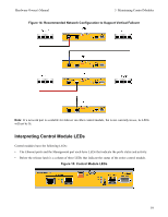
Hardware Owner's Manual 3 Maintaining Control Modules Table 5: Ethernet and Management Port LED Descriptions 10GBASE-T Ethernet LED Location State Description Left (Link) Off No power, not connected to network, or passive. On Connected to network. Right (Act) Off No power, not transmitting, or not receiving. On Transmitting or receiving. SPF+ Ethernet LED Location State Description Top (Link) Off No power, not connected to network, or passive. On Connected to network. Bottom (Act) Management LED Location Off On State No power, not transmitting, or not receiving. Transmitting or receiving. Description Left (Link) Off No power or not connected to network. On Connected to network. Right (Act) Off No power, not transmitting, or not receiving. On Transmitting or receiving. LED Name PWR ACT ERR Table 6: Control Module Status LED Descriptions State Description Off No power. On (steady green) Power/OK. Off No power, secondary control module is not synchronized with active control module, or error condition. Steady green Steady amber Off Steady red Blinking red Active control module (serving network I/O). Secondary control module. Cache is synchronized with active control module. Normal operation or no power. Array is starting up, in error condition, or in Standby mode. Array is entering power standby mode because the Standby On/Off button was pressed. Identifying Control Module Failures You can identify a failure in a control module by: • LEDs on the control module itself. See Interpreting Control Module LEDs on page 19. • Messages on the console, in the event log, or in the Group Manager GUI Alarms panel. 20
-
 1
1 -
2
-
3
-
4
-
5
-
6
-
7
-
8
-
9
-
10
-
11
-
12
-
13
-
14
-
15
-
16
-
17
-
18
-
 19
19 -
 20
20 -
 21
21 -
 22
22 -
 23
23 -
 24
24 -
 25
25 -
 26
26 -
 27
27 -
 28
28 -
 29
29 -
30
-
31
-
32
-
33
-
34
-
35
-
36
-
37
-
38
-
39
-
40
-
41
-
42
-
43
-
44
-
45
-
46
-
47
-
48
 |
 |
