Dell Equallogic PS4110X PS4110 Hardware Owners Manual - Page 9
Back-Panel Features and Indicators, Shutting Down and Restarting an Array
 |
View all Dell Equallogic PS4110X manuals
Add to My Manuals
Save this manual to your list of manuals |
Page 9 highlights
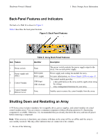
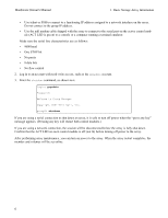
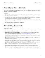
Hardware Owner's Manual 1 Basic Storage Array Information Back-Panel Features and Indicators The back of a PS4110 is shown in Figure 5. Table 2 describes the back panel features. Figure 5: Back Panel-Features Item Feature 1 Power switch 2 Power supply unit (PSU) 3 Control Module 4 Control Module Release Lever Table 2: Array Back Panel Features Identifier Description None PSU0 (left) PSU1 (right) CM0 (top) CM1 (bottom) None The power switch controls the power supply output to the array. One on each power supply. Power supply and cooling fan module for array. For more information, see Power Supply LEDs on page 33. The control module provides: • a data path between the array and the applications using the storage • array management functions for your array Enables you to remove the control module from the array. Shutting Down and Restarting an Array A PS Series array includes redundant, hot-swappable drives, power supplies, and control modules (in a dual control module array). You can remove a redundant component without affecting operation if a functioning component is available. Otherwise, it is recommended that you cleanly shut down the array and turn off power before removing a component. Note: When an array is shut down, any volumes with data on the array will be set offline until the array is successfully restarted. This may affect initiators that are connected to the volumes. 1. Do one of the following: 5
-
 1
1 -
2
-
3
-
 4
4 -
 5
5 -
 6
6 -
 7
7 -
 8
8 -
 9
9 -
 10
10 -
 11
11 -
 12
12 -
 13
13 -
 14
14 -
15
-
16
-
17
-
18
-
19
-
20
-
21
-
22
-
23
-
24
-
25
-
26
-
27
-
28
-
29
-
30
-
31
-
32
-
33
-
34
-
35
-
36
-
37
-
38
-
39
-
40
-
41
-
42
-
43
-
44
-
45
-
46
-
47
-
48
 |
 |
