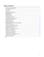
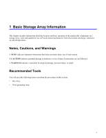
Dell Equallogic PS4110X PS4110 Hardware Owners Manual - Page 8
Hardware Owner's Manual, Front Panel Features and Indicators 3.5-inch Drives
 |
View all Dell Equallogic PS4110X manuals
Add to My Manuals
Save this manual to your list of manuals |
Page 8 highlights
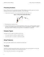
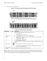
Hardware Owner's Manual 1 Basic Storage Array Information Table 1 describes the front panel features. Figure 3: Front Panel Features and Indicators (3.5-inch Drives) Figure 4: Front Panel Features and Indicators (2.5-inch Drives) Item Indicator 1 Array status LED Table 1: Front Panel Feature Descriptions Icon Description The array status LED lights when the array power is on. • Off-No power. • Steady blue-Array status is OK. • Slow blinking blue-Array status is Standby mode. • Blinking blue-Administrator request to identify the array (see the Group Manager online help). • Steady amber-Critical status. • Blinking amber-Warning. The power LED is ON when at least one power supply is supplying power to the array. 2 Power LED • Off-No power, or the array is in Standby mode. • Steady green-Array has at least one power supply providing power, and array is not in Standby mode. 3 Drive Release Latch None Enables you to remove a drive from the array. Note: The LEDs are part of a built-in chassis control panel that is not hot-swappable and can be replaced only by support personnel. During the array power-up sequence, these LEDs will cycle through different states until the array is fully started and the active control module has been determined. 4
-
 1
1 -
2
-
 3
3 -
 4
4 -
 5
5 -
 6
6 -
 7
7 -
 8
8 -
 9
9 -
 10
10 -
 11
11 -
 12
12 -
 13
13 -
14
-
15
-
16
-
17
-
18
-
19
-
20
-
21
-
22
-
23
-
24
-
25
-
26
-
27
-
28
-
29
-
30
-
31
-
32
-
33
-
34
-
35
-
36
-
37
-
38
-
39
-
40
-
41
-
42
-
43
-
44
-
45
-
46
-
47
-
48
 |
 |
