Dell Equallogic PS4110X PS4110 Hardware Owners Manual - Page 22
About Control Module Configurations, Single Controller Configuration
 |
View all Dell Equallogic PS4110X manuals
Add to My Manuals
Save this manual to your list of manuals |
Page 22 highlights
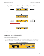
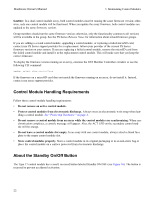
Hardware Owner's Manual 3 Maintaining Control Modules • A release button and latch to release the control module from the array for replacement. The release lever has a switch that detects activation and prompts the array to save data to non-volatile storage, thereby protecting your data. Caution: Do not mix control module types in an array. Always make sure both control modules are the same type and color. See the latest PS Series Release Notes for information about other supported control modules. About Control Module Configurations While an array can run using only one control module, it is not recommended as this creates a single point of failure. If the control module fails and there is no other to take over, all access to your volumes stops until you replace it. Only one control module is active (serving network traffic) at one time. The secondary (redundant) control module mirrors cache data from the active control module. If the active control module fails, the secondary will take over network operations. Single Controller Configuration A single control module is a single point of failure. If the control module fails, the entire array (and all the volumes on it) becomes unavailable. Dell strongly recommends buying an array with two control modules, or installing a second control module in a single-controller array. In an array with a single control module, the module must be in slot CM0. Caution: For proper array cooling and airflow requirements, there must be a blank filler in the empty control module slot. Dual Controller Configuration A dual control module configuration eliminates a single point of failure in the array. If the active control module fails, the secondary control module takes over immediately with no interruption of service. This gives you time to replace the failed control module while your volumes and data remain accessible. In addition, a dual control module configuration supports a feature called vertical failover. An Ethernet port on the active control module can fail over to the same Ethernet port on the secondary control module if a network path fails. For example, if Ethernet 0 on CM0 loses connectivity (switch 0 fails), Ethernet 0 on CM1 takes over. Figure 14 illustrates the recommended configuration to support vertical failover. 18
-
 1
1 -
2
-
3
-
4
-
5
-
6
-
7
-
8
-
9
-
10
-
11
-
12
-
13
-
14
-
15
-
16
-
 17
17 -
 18
18 -
 19
19 -
 20
20 -
 21
21 -
 22
22 -
 23
23 -
 24
24 -
 25
25 -
 26
26 -
 27
27 -
28
-
29
-
30
-
31
-
32
-
33
-
34
-
35
-
36
-
37
-
38
-
39
-
40
-
41
-
42
-
43
-
44
-
45
-
46
-
47
-
48
 |
 |
