Dell Equallogic PS4110X PS4110 Hardware Owners Manual - Page 41
Inserting a Power Supply and Cooling Module
 |
View all Dell Equallogic PS4110X manuals
Add to My Manuals
Save this manual to your list of manuals |
Page 41 highlights
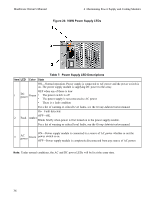
Hardware Owner's Manual 4 Maintaining Power Supply and Cooling Modules Figure 25: Inserting a Power Supply and Cooling Module 3. Make sure the power switch is in the OFF position. 4. Connect the power cable to the power supply and cooling module and plug the cable into a power outlet. Note: The AC LED lights up when the AC power cable is connected, even if the switches on the power supply are off. 5. Secure the power cable using the hook-and-loop fastener strap, as shown in the following illustration. 6. Turn on the switch on the power supply and cooling module. 37
-
 1
1 -
2
-
3
-
4
-
5
-
6
-
7
-
8
-
9
-
10
-
11
-
12
-
13
-
14
-
15
-
16
-
17
-
18
-
19
-
20
-
21
-
22
-
23
-
24
-
25
-
26
-
27
-
28
-
29
-
30
-
31
-
32
-
33
-
34
-
35
-
 36
36 -
 37
37 -
 38
38 -
 39
39 -
 40
40 -
 41
41 -
 42
42 -
 43
43 -
 44
44 -
 45
45 -
 46
46 -
47
-
48
 |
 |

Hardware Owner's Manual
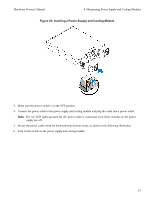
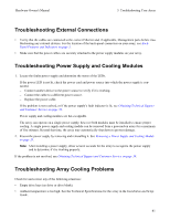
4 Maintaining Power Supply and Cooling Modules
Figure 25: Inserting a Power Supply and Cooling Module
3.
Make sure the power switch is in the OFF position.
4.
Connect the power cable to the power supply and cooling module and plug the cable into a power outlet.
Note:
The AC LED lights up when the AC power cable is connected, even if the switches on the power
supply are off.
5.
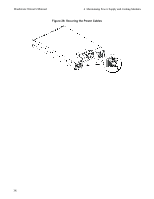
Secure the power cable using the hook-and-loop fastener strap, as shown in the following illustration.
6.
Turn on the switch on the power supply and cooling module.
37