Dell OptiPlex NX1 Service Manual
Dell OptiPlex NX1 Manual
 |
View all Dell OptiPlex NX1 manuals
Add to My Manuals
Save this manual to your list of manuals |
Dell OptiPlex NX1 manual content summary:
- Dell OptiPlex NX1 | Service Manual - Page 1
- Dell OptiPlex NX1 | Service
Manual - Page 2
strictly forbidden. Trademarks used in this text: Dell, the DELL logo, and OptiPlex are registered trademarks of Dell Computer Corporation; Intel and Pentium are registered trademarks and MMX is a trademark of Intel Corporation; Microsoft, Windows, and MS-DOS are registered trademarks of Microsoft - Dell OptiPlex NX1 | Service
Manual - Page 3
Integrated Diskette/Tape Drive Controller 1-4 Integrated Support (Optional 1-6 Network Cable Requirements 1-7 Full Set of I/O Ports 1-7 UPS 1-7 Location of Major Components 1-7 Advanced Expansion Features 1-12 OptiPlex NX1 Computer Service Information 1-16 Remote Management Support Features (Optional - Dell OptiPlex NX1 | Service
Manual - Page 4
1-19 DMA Channel Assignments 1-20 Hard-Disk Drive Service Information 1-20 Hard-Disk Drive for the Low-Profile Computer 1-21 Hard-Disk Drive for the Midsize Computer 1-21 Hard-Disk Drive for the Mini Tower Computer 1-22 Hard-Disk Drive for the OptiPlex NX1 Computer 1-22 Power-Supply - Dell OptiPlex NX1 | Service
Manual - Page 5
Eject, Power, and Reset Buttons 4-4 Front-Panel Inserts 4-5 Control Panel 4-6 Drives 4-7 Externally Accessible Drive Assemblies 4-7 3.5-Inch Diskette Drive Assembly 4-8 5.25-Inch Drive Assembly 4-9 Hard-Disk Drive Assembly 4-10 System Power Supply 4-11 Expansion Cards 4-12 Expansion-Card - Dell OptiPlex NX1 | Service
Manual - Page 6
, and Reset Buttons 6-6 Front-Panel Inserts 6-7 Control Panel 6-9 Drives 6-10 Externally Accessible Drive Assemblies 6-10 3.5-Inch Diskette Drive Assembly 6-11 5.25-Inch Drive Assembly 6-12 Hard-Disk Drive Bracket 6-14 Hard-Disk Drive 6-15 System Power Supply 6-16 Expansion Cards 6-17 - Dell OptiPlex NX1 | Service
Manual - Page 7
Inside the Computer 7-2 Optional Stand 7-3 Computer Cover 7-4 Control Panel 7-6 Hard-Disk Drive 7-7 System Power Supply 7-8 Expansion-Card Cage 7-9 Expansion Card 7-10 Mini Tower Chassis 1-11 Internal View of the OptiPlex NX1 Chassis 1-12 Riser Board for the OptiPlex NX1 Computer 1-13 ix - Dell OptiPlex NX1 | Service
Manual - Page 8
1-31 DC Power Connector P3 for the OptiPlex NX1 Computer 1-31 DC Power Cables for the OptiPlex NX1 Computer 1-31 DC Power Distribution for the OptiPlex NX1 Computer . . . . 1-32 Connecting an External Diskette Drive to the OptiPlex NX1 Computer 2-9 Internal View of the Low-Profile Computer - Dell OptiPlex NX1 | Service
Manual - Page 9
Front-Panel Insert Removal 5-7 Control Panel Removal 5-8 Drive Hardware 5-9 3.5-Inch Diskette Drive Removal 5-10 5.25-Inch Drive Assembly Removal 5-11 5.25-Inch Drive Removal 5-11 Hard-Disk Drive Bracket Removal 5-12 Hard-Disk Drive Removal 5-13 System Power-Supply Removal 5-14 Expansion - Dell OptiPlex NX1 | Service
Manual - Page 10
Sink Removal 6-24 System Battery Installation 6-25 Internal View of the OptiPlex NX1 Computer 7-3 Optional-Stand Removal 7-3 Computer Cover Removal 7-4 Service Access Lock 7-5 Control Panel Removal 7-6 Hard-Disk Drive Removal 7-7 System Power-Supply Removal 7-8 Expansion-Card Cage Removal - Dell OptiPlex NX1 | Service
Manual - Page 11
xiii - Dell OptiPlex NX1 | Service
Manual - Page 12
techniques. In addition to information provided in this manual and the User's Guide that came with the system, Dell provides the Diagnostics and Troubleshooting Guide for troubleshooting procedures and instructions on using the Dell diagnostics to test the computer system. Throughout this - Dell OptiPlex NX1 | Service
Manual - Page 13
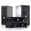
This manual contains field-servicing information for the Dell® OptiPlex® GX1 Managed PC and OptiPlex NX1 Net PC family of computers. The Dell OptiPlex GX1 and OptiPlex NX1 systems are high-speed (266-, 333-, 350-, or 400-MHz), upgradable desktop computers built around high-performance Intel® Pentium - Dell OptiPlex NX1 | Service
Manual - Page 14
Midsize Chassis Mini Tower Chassis OptiPlex NX1 Chassis The three OptiPlex GX1 and the OptiPlex NX1 chassis configurations differ primarily in the following expansion features: Number of expansion slots available for PCI/ISA expansion cards Number of available internal drive bays for EIDE/SCSI - Dell OptiPlex NX1 | Service
Manual - Page 15
A). However, the OptiPlex NX1 computer has no built-in diskette drive and requires a special a technique called single instruction, multiple data (SIMD Dell Computer Corporation for information about Dell-supported microprocessor upgrades. For additional performance, the OptiPlex GX1 and OptiPlex NX1 - Dell OptiPlex NX1 | Service
Manual - Page 16
Drive Service Information" found later in this chapter. The OptiPlex NX1 system supports only one hard-disk drive and optionally one external diskette drive for running the diskette-based diagnostics as described in Chapter 2,"Basic Troubleshooting". As a standard feature, OptiPlex GX1 and OptiPlex - Dell OptiPlex NX1 | Service
Manual - Page 17
an external diskette-drive kit as described in Chapter 2, "Basic Troubleshooting." The OptiPlex GX1 and OptiPlex NX1 systems include an PCI bus providing greater performance for devices attached to the PCI bus. The maximum supported resolution is 1600 x 1200 with 65,535 colors at 75 Hz. The SVGA - Dell OptiPlex NX1 | Service
Manual - Page 18
information on resetting the chassis intrusion detector. The OptiPlex GX1 systems and OptiPlex NX1 systems are available with or without integrated Ethernet NIC subsystem. The integrated 10/100-Mbps 3Com® PCI 3C905B-TX Ethernet NIC subsystem supports the Wakeup On LAN feature and the 10BASE-T and - Dell OptiPlex NX1 | Service
Manual - Page 19
the Reference and Installation Guide provides instructions for connecting the computer to, and configuring it for use on, an Ethernet network. For OptiPlex NX1 systems, refer to the online Network Administrator's Guide. For desktop connectivity, the OptiPlex GX1 and OptiPlex NX1 systems include the - Dell OptiPlex NX1 | Service
Manual - Page 20
power indicator reset button hard-disk drive access indicator Midsize Chassis diskette-drive access indicator power button reset button power indicator hard-disk drive access indicator Mini Tower Chassis OptiPlex NX1 Chassis power button power indicator hard-disk drive access indicator 1-8 - Dell OptiPlex NX1 | Service
Manual - Page 21
connector mouse connector keyboard connector USB connectors (2) serial port 2 connector 3.5-inch diskette drive diskette/tape drive interface cable hard-disk drive interface cable hard-disk drive chassis intrusion switch audio connectors (3) NIC connector (optional) video connector security cable - Dell OptiPlex NX1 | Service
Manual - Page 22
bracket AC power receptacle voltage selection switch padlock ring chassis intrusion switch hard-disk drive interface cable parallel port connector serial port 1 connector mouse connector keyboard connector USB connectors (2) serial port 2 connector expansion-card cage expansion-card slots - Dell OptiPlex NX1 | Service
Manual - Page 23
mouse connector USB connectors (2) serial port 2 connector video connector NIC connector (optional) audio connectors (3) padlock ring power supply external drive bays hard-disk drive bracket interface cable chassis intrusion switch expansion-card cage system board riser board System Overview 1-11 - Dell OptiPlex NX1 | Service
Manual - Page 24
connectors (2) serial port 2 connector hard-disk drive expansion-card cage expansion-card slot security cable slot AC power receptacle NIC connector (optional) video connector The OptiPlex GX1 systems contain advanced expansion subsystems that can support a mixture of traditional ISA expansion - Dell OptiPlex NX1 | Service
Manual - Page 25
The OptiPlex NX1 computer has one PCI expansion-card connector on the riser board (see supports an optional NIC expansion card with Wakeup On LAN capability. The power LED lights up when DC power is applied to the riser board. power LED Wakeup On LAN power connector PCI1 connector The OptiPlex - Dell OptiPlex NX1 | Service
Manual - Page 26
board, with a PCI-to-PCI bridge. Option 2 has two ISA expansion-card connectors and five PCI expansion-card connectors. Two PCI/ISA expansion-card connector pairs each share an expansion-card slot, again resulting in a total of five expansion-card slots (see Figure 1-10). Both riser board options - Dell OptiPlex NX1 | Service
Manual - Page 27
in the following subsections, and installation procedures are provided for the various chassis configurations in Chapters 4, 5, 6, and 7. On the OptiPlex GX1 and OptiPlex NX1 systems, the microprocessor and secondary L2 cache memory are implemented in an SEC cartridge/heat sink assembly. Upgrade to - Dell OptiPlex NX1 | Service
Manual - Page 28
Download and run the diagnostics over the network Dell OptiPlex GX1 computers are shipped with an online System User's Guide (located in the Dell Accessories folder) that provides additional hardware and software installation, configuration information, and Dell contact information. OptiPlex NX1 - Dell OptiPlex NX1 | Service
Manual - Page 29
diagnostics are available to aid in troubleshooting all major components of the three Dell OptiPlex GX1 chassis. The OptiPlex NX1 systems use server-based diagnostics, hard-disk-based diagnostics, or the diskette-based diagnostics using an external diskette-drive kit connected directly to the system - Dell OptiPlex NX1 | Service
Manual - Page 30
jumpered unjumpered RSVD1 Reserved Jumper not installed (default). 450MHZ* Microprocessor speed Reserved. Jumper not installed (default). 400MHZ* Microprocessor speed Install jumper if the microprocessor's internal speed is 400 MHz; otherwise, the jumper should not be installed. 350MHZ* - Dell OptiPlex NX1 | Service
Manual - Page 31
that the device connected to the serial port (COM1 or COM3) requires service. Available for use by an expansion card. Generated by super I/O controller to indicate that diskette or tape drive requires service. Generated by super I/O controller to indicate that device connected to parallel port - Dell OptiPlex NX1 | Service
Manual - Page 32
, NIC (optional), and video controllers are assigned available DMA channels automatically during system start-up. The following subsections provide service-related information about hard-disk drive options for the OptiPlex GX1 (low-profile, midsize, and mini tower) and OptiPlex NX1 computers. 1-20 - Dell OptiPlex NX1 | Service
Manual - Page 33
right side front Low-Profile Chassis top back front OptiPlex NX1 Chassis back left side front right side bottom Mini Tower Chassis front Midsize Chassis The hard-disk drive assembly (consisting of the hard-disk drive and the harddisk drive bracket) is located inside the chassis at the left - Dell OptiPlex NX1 | Service
Manual - Page 34
1-inch-high EIDE or SCSI hard-disk drives, or one 1-inch-high EIDE or SCSI hard-disk drive and one 1.6-inch-high EIDE or SCSI hard-disk drive. One 1-inch-high EIDE hard-disk drive can be mounted to the tower computers. 2 Withstands surges of up to 11.0 A to support disk start-up operations. 1-22 - Dell OptiPlex NX1 | Service
Manual - Page 35
-12 VDC -10.80 to -13.20 VDC 0.3 A (low-profile computers); 0.3 A (midsize and mini tower computers) -5 VDC -4.50 to -5.50 VDC 0.3 A (low-profile computers); 0.3 A (midsize and mini tower computers) +5 VFP3 +4.75 to +5.25 VDC 10 mA 3 VFP (volts flea power) - sometimes called "standby power - Dell OptiPlex NX1 | Service
Manual - Page 36
) Figures 1-18 through 1-22 provide the following information about DC power distribution: Power-supply connector identification Power cable connections for diskette, tape, CD-ROM, and hard-disk drives Power distribution to sockets and connectors on the system board 1-24 - Dell OptiPlex NX1 | Service
Manual - Page 37
P4 P3 P5 P1 P2 System Overview 1-25 - Dell OptiPlex NX1 | Service
Manual - Page 38
1-26 - Dell OptiPlex NX1 | Service
Manual - Page 39
P6 P4 P5 P9 P3 P2 P1 P7 System Overview 1-27 - Dell OptiPlex NX1 | Service
Manual - Page 40
-12 VDC PCI1 through PCI3 P1 ISA1 through ISA3 +12 VDC FAN internal P2 hard-disk drive internal P3 hard-disk drive P4 3.5-inch diskette drive P5* optional drive P6* optional drive main memory DIMM_A DIMM_B DIMM_C +5 VFP +5 VDC +5 VDC +5 VDC +5 VDC MICROPROCESSOR processor core regulator - Dell OptiPlex NX1 | Service
Manual - Page 41
ISA4 internal P2 hard-disk drive internal P3 hard-disk drive P4 3.5-inch diskette drive P5 optional drive P6 optional drive P9 optional drive +12 VDC on the system board and to P1 on the riser board. The OptiPlex NX1 computers have an 80-W computer power supply. The power supply can operate - Dell OptiPlex NX1 | Service
Manual - Page 42
+4.75 to +5.25 VDC 1.2 A 1 The combined load on the +5-VDC and +3.3-VDC outputs should not exceed 65 W. 2 Withstands surges of up to 3.0 A to support disk start-up operations. 3 VFP (volts flea power) - sometimes called "standby power." The power-supply output voltages can be measured at the back - Dell OptiPlex NX1 | Service
Manual - Page 43
(black) +12 VDC (yellow) Figures 1-26 and 1-27 provide the following information about DC power distribution: Power-supply connector identification Power cable connection for the hard-disk drive Power distribution to sockets and connectors on the system board P3 P2 P1 System Overview 1-31 - Dell OptiPlex NX1 | Service
Manual - Page 44
POWER_2 +3.3 VDC +3.3 VDC +5 VDC +12 VDC -12 VDC RISER +3.3 VDC +5 VDC +12 VDC -12 VDC riser board P1 PCI1 internal P3 hard-disk drive +12 VDC main memory sockets DIMM_A DIMM_B DIMM_C +5 VFP +5 VDC +5 VDC +5 VDC +5 VDC MICROPROCESSOR processor core regulator +3.3 VDC core VCC +2.1 to - Dell OptiPlex NX1 | Service
Manual - Page 45
/100 MHz 32-KB (16-KB data cache and 16-KB instruction cache) internal to the microprocessor System chip set Data bus width connectors: Low-profile computers Midsize computers . . . . Mini tower computers OptiPlex NX1 computers PCI and ISA (PCI bus complies with PCI Specification 2.1) PCI: - Dell OptiPlex NX1 | Service
Manual - Page 46
computers Midsize computers . . . . Mini tower computers OptiPlex NX1 computers two (one ISA connector and one PCI connector inch bay for a 3.5-inch diskette drive; one 5.25-inch bay for a diskette, tape, or CD-ROM drive one 3.5-inch bay for a 3.5-inch diskette drive; two 5.25-inch bays for - Dell OptiPlex NX1 | Service
Manual - Page 47
Mini tower computers OptiPlex NX1 computers Internal hard-disk drive bays: Low-profile computers Midsize computers . . . . Mini tower computers OptiPlex NX1 computers one 3.5-inch bay for a 3.5-inch diskette drive; three 5.25-inch bays for diskette, tape, or CD-ROM drives none one bay for a - Dell OptiPlex NX1 | Service
Manual - Page 48
GX1 and OptiPlex NX1 systems) USB two USB-compliant connectors Audio line-in 2.0-V rms (maximum); stereo Audio microphone . . . . . 89-mV rms (maximum); mono Audio line-out 1.4-V rms (maximum); stereo (at 32 ohms minimum impedance) Internally accessible: EIDE hard-disk drive. . . . two 40 - Dell OptiPlex NX1 | Service
Manual - Page 49
Hard-disk drive access indicator green LED Link integrity indicator (onsystemswithNICconnector) green LED Activity indicator (onsystemswithNICconnector) yellow LED Power supply wattage: Low-profile computers 145 W Midsize computers . . . . 200 W Mini tower computers 200 W OptiPlex NX1 computers - Dell OptiPlex NX1 | Service
Manual - Page 50
Depth Weight (minimum) . . . . . Midsize computers: Height Width Depth Weight (minimum) . . . . . Mini tower computers: Height Width Depth Weight (minimum) . . . . . OptiPlex NX1 computers: Height Width Depth Weight 10.9 cm (4.3 inches) 40.89 cm (16.1 inches) 43.69 cm (17.2 inches) 10 - Dell OptiPlex NX1 | Service
Manual - Page 51
Maximum shock: Operating left side (for low-profile, midsize, and OptiPlex NX1 computers operating in a vertical orientation) and bottom half-sine pulse with a change in velocity of 20 inches/sec (50.8 cm/sec) Storage 27-G faired square - Dell OptiPlex NX1 | Service
Manual - Page 52
1-40 - Dell OptiPlex NX1 | Service
Manual - Page 53
This chapter provides basic troubleshooting procedures applicable to all systems of the Dell OptiPlex GX1 Managed PC and OptiPlex NX1 Net PC families. A brief explanation of how to load and start the system diagnostics is also provided at the end of the chapter. Dell recommends that you perform the - Dell OptiPlex NX1 | Service
Manual - Page 54
Is the problem a result of user error? Yes. Instruct the user in the proper procedure, or direct him or her to the appropriate user documentation for the correct procedure. No. Proceed to the next - Dell OptiPlex NX1 | Service
Manual - Page 55
the system several times in order to complete all of these steps. To observe problem indications during the boot routine, follow these steps: Does the fan run normally? Yes. Proceed to step 3. No. Troubleshoot the system power supply. Do these indicators flash on and off within approximately 10 - Dell OptiPlex NX1 | Service
Manual - Page 56
either of these indicators fails to light up during the boot routine, troubleshoot the diskette drive or hard-disk drive subsystem, as appropriate. System error messages: These messages can indicate problems or provide status information. If a system error message is displayed, see Table 3-2. Beep - Dell OptiPlex NX1 | Service
Manual - Page 57
your system. For information about these jumpers, see "System Board Jumpers" in Chapter 1. Does the problem appear to be resolved? Yes. No further steps are necessary. Terminate the procedure. No. Proceed to exist, check the system and reassign the resources as necessary. Basic Troubleshooting 2-5 - Dell OptiPlex NX1 | Service
Manual - Page 58
OptiPlex NX1 systems use either server-based, hard-disk-based, or (optionally) diskette-based diagnostics using an external diskette-drive Device List screen (see Figure A-2). Then move the LANDesk Service Agent category above the Hard Drive C: category in the Boot Device Priority list. Press - Dell OptiPlex NX1 | Service
Manual - Page 59
and the storage capability of the hard-disk drive For a complete description of the server-based diagnostics, see "Server-Based Diagnostics" in the online Network Administrator's Guide. The hard-disk-based diagnostics contains tests that aid in troubleshooting all major components of the system - Dell OptiPlex NX1 | Service
Manual - Page 60
subsystem If the Diagnostics Menu does not appear, check with the network administrator to determine if the service partition was removed from the hard-disk drive. If it is not possible to run the hard-disk-based diagnostics and if you are prepared to remove the computer cover, see "Internal Visual - Dell OptiPlex NX1 | Service
Manual - Page 61
The OptiPlex NX1 systems use either server-based, hard-disk-based or optionally diskette-based diagnostics using an external diskette-drive kit hard-disk-based diagnostics. These tests aid in troubleshooting all major components of the system. hard-disk drive external diskette drive diskette drive - Dell OptiPlex NX1 | Service
Manual - Page 62
To install the external diskette drive, follow these steps: To run the diskette-based diagnostics, follow these steps: Starting the diagnostics causes the Dell logo to appear on the monitor screen, followed by a message indicating that the diagnostics is loading. Before the diagnostics loads, a - Dell OptiPlex NX1 | Service
Manual - Page 63
-based, hard-disk-based, or diskette-based diagnostics reveals the source of the problem or leads to the proper troubleshooting steps for determining the source of the problem, call Dell for technical assistance. For instructions, see "Contacting Dell" in the online Network Administrator's Guide or - Dell OptiPlex NX1 | Service
Manual - Page 64
2-12 - Dell OptiPlex NX1 | Service
Manual - Page 65
error messages that are common to all members of the Dell OptiPlex GX1 Managed PC and OptiPlex NX1 Net PC family of computers. These error messages can the source of the problem, run the appropriate tests in the system diagnostics to assist in troubleshooting the problem. 1-1-3 1-1-4 1-2-1 1-2-2 - Dell OptiPlex NX1 | Service
Manual - Page 66
1-3-1 1-3-2 1-3-3 1-3-4 1-4-1 1-4-2 2-1-1 through 2-4-4 3-1-1 3-1-2 3-1-3 3-1-4 3-2-4 3-3-4 3-4-1 3-4-2 4-2-1 4-2-2 4-2-3 4-2-4 4-3-1 4-3-3 Main-memory refresh verification failure No memory installed Chip or data line failure in the first 64 KB of main memory Faulty or improperly seated DIMM or - Dell OptiPlex NX1 | Service
Manual - Page 67
error is detected by the system. System messages are very useful in troubleshooting the system. Some of these messages require operator intervention to solve; drive or harddisk drive controller detected uncorrectable read error. Faulty diskette/tape drive subsystem or hard-disk drive subsystem - Dell OptiPlex NX1 | Service
Manual - Page 68
execute command. Operating system corrupted or not installed properly. Hard-disk drive failed to initialize. Incorrect configuration settings in System Setup program, improperly connected hard-disk drive cable, faulty hard-disk drive controller subsystem (defective system board), or loose power - Dell OptiPlex NX1 | Service
Manual - Page 69
System Setup program contains incorrect system configuration settings. Incorrect configuration settings in System Setup program or faulty battery. System cannot communicate with keyboard. Keyboard cable connector loose or improperly connected, defective keyboard, or defective keyboard/mouse - Dell OptiPlex NX1 | Service
Manual - Page 70
not have bootable operating system installed on it. Faulty diskette, diskette/ tape drive subsystem, or hard-disk drive subsystem. No operating system on No operating system on diskette. diskette. System encountered problem in trying to configure one or more expansion cards. System resource - Dell OptiPlex NX1 | Service
Manual - Page 71
in System Setup program incorrect or system battery bad. Timer circuit on system board malfunctioning. Defective diskette or hard-disk drive. Faulty diskette or harddisk drive. Defective system board. Defective battery or faulty chip (defective system board). Incorrect Time or Date settings or - Dell OptiPlex NX1 | Service
Manual - Page 72
3-8 - Dell OptiPlex NX1 | Service
Manual - Page 73
This chapter provides procedures for removing the components, assemblies, and subassemblies in the Dell OptiPlex GX1 low-profile computer. If you are servicing a midsize, mini tower, or OptiPlex NX1 Net PC chassis, use Chapter 5, 6, or 7, as appropriate for your system. Unless otherwise noted, each - Dell OptiPlex NX1 | Service
Manual - Page 74
Figure 4-1 shows an internal view of the interior of the low-profile computer and identifies major components for orientation. Refer to this illustration, as needed, when performing the component removal/replacement procedures in this chapter. 4-2 - Dell OptiPlex NX1 | Service
Manual - Page 75
CD-ROM drive in external bay power supply system board securing buttons (2) diskette drive drive cage for external drive internal harddisk drive chassis intrusion switch expansion-card cage front of computer Removing and Replacing Parts on the Low-Profile Chassis 4-3 - Dell OptiPlex NX1 | Service
Manual - Page 76
To remove the computer cover, follow these steps: Three plastic hooks on the inside-front part of the cover secure it to the chassis. Before you reinstall the cover, fold all cables out of the way so that they do not interfere with the cover or with proper airflow inside the computer. computer - Dell OptiPlex NX1 | Service
Manual - Page 77
When these clips are released, the button comes free from the front panel of the cover. computer cover (upside down) 5.25-inch front-panel insert posts (2) ring-tabs (2) To remove a front-panel insert, follow these steps: To replace a 5.25-inch front-panel insert, position the two ring-tabs over - Dell OptiPlex NX1 | Service
Manual - Page 78
mounting screw control panel cable control panel chassis mounting tab To remove the control panel, follow these steps: When you reinstall the control panel, be sure to put the right side of the control panel behind the mounting tab. 4-6 - Dell OptiPlex NX1 | Service
Manual - Page 79
any of the procedures in the following subsections. DC power cable diskette/tape drive interface cable power supply 3.5-inch diskette drive 5.25-inch drive bay and bracket hard-disk drive DSKT connector EIDE cable secondary EIDE interface connector (IDE2) primary EIDE interface connector - Dell OptiPlex NX1 | Service
Manual - Page 80
latches (2) front of computer hooks (2) To remove the 3.5-inch diskette drive assembly, follow these steps: Rotate the left side of the assembly up, and lift the assembly out of the chassis. When you replace the 3.5-inch diskette drive, be sure that the mounting holes on the right side of the - Dell OptiPlex NX1 | Service
Manual - Page 81
, and tighten the screws in the order stamped on the bottom of the bracket. Check the alignment of the computer cover around the 5.25-inch drive bezel. Adjust the drive forward or backward on the bracket to align it. Removing and Replacing Parts on the Low-Profile Chassis 4-9 - Dell OptiPlex NX1 | Service
Manual - Page 82
mounting screws (4) tabs (2) front of computer notches (2) To remove the hard-disk drive, follow these steps: When you reinstall the hard-disk drive assembly, be sure that the tabs on the back of the mounting plate fully engage the notches on the chassis-before you rotate the assembly - Dell OptiPlex NX1 | Service
Manual - Page 83
power supply power-supply mounting screw To remove the system power supply, follow these steps: When you replace the system power supply, place it down inside the chassis and against the right side of the chassis. Then slide the system power supply toward the back of the chassis, and hook the tabs - Dell OptiPlex NX1 | Service
Manual - Page 84
cage contains the riser board and any installed expansion cards. Dell recommends that you remove the expansion-card cage first before removing the expansion cards. lever expansion-card cage ISA expansion-card end support side support hole notch To remove an expansion-card cage, follow these steps - Dell OptiPlex NX1 | Service
Manual - Page 85
expansion card expansion-card connector retaining screw card-mounting bracket card-slot opening riser board To remove an expansion card, follow these steps: Removing and Replacing Parts on the Low-Profile Chassis 4-13 - Dell OptiPlex NX1 | Service
Manual - Page 86
riser-board mounting screws (2) riser board riser-board alignment slot expansion-card cage To remove the riser board, follow these steps: When you replace the riser board, be sure that the alignment feature on the expansion-card cage engages with the alignment slot. 4-14 - Dell OptiPlex NX1 | Service
Manual - Page 87
the system board, remove all DIMMs, the video-memory upgrade module (if present), the single-edge contact (SEC) cartridge/heat sink assembly, and the guide bracket assembly from the old system board and install them on the replacement board. Also, set the jumpers on the new system board so that - Dell OptiPlex NX1 | Service
Manual - Page 88
-DIMM_C) main power input connector (POWER_1) 3.3-V power input connector (POWER_2) system board jumpers primary EIDE diskette/tape drive interface connector interface connector (IDE1) (DSKT) front of computer battery socket (BATTERY) chassis-intrusion switch connector (INTRUSION) control - Dell OptiPlex NX1 | Service
Manual - Page 89
To remove a DIMM from one of the three DIMM sockets, follow these steps: securing clips (2) 2. 1. securing clips (2) 2. 1. Removing and Replacing Parts on the Low-Profile Chassis 4-17 - Dell OptiPlex NX1 | Service
Manual - Page 90
notch video-memory upgrade socket video-memory upgrade module You can upgrade video memory from 4 to 8 MB by installing a video-memory upgrade module in the video-memory upgrade socket on the system board. Adding additional video memory increases the system's video performance and provides - Dell OptiPlex NX1 | Service
Manual - Page 91
you can replace the microprocessor on your system board with any Dell-supported microprocessor upgrade. The microprocessor upgrade kit is shipped with an (2) heat sink SEC cartridge securing clips (2) guide bracket assembly metal standoffs (2) Removing and Replacing Parts on the Low- - Dell OptiPlex NX1 | Service
Manual - Page 92
To remove the SEC cartridge/heat sink assembly, follow these steps: NOTE: When installing the SEC cartridge/heat sink assembly, carefully orient the assembly and press firmly with up to 25 pounds of force to mate the SEC cartridge with its connector. Then slide the SEC cartridge release latches - Dell OptiPlex NX1 | Service
Manual - Page 93
Removing and Replacing Parts on the Low-Profile Chassis 4-21 - Dell OptiPlex NX1 | Service
Manual - Page 94
4-22 - Dell OptiPlex NX1 | Service
Manual - Page 95
This chapter provides procedures for removing the components, assemblies, and subassemblies in the Dell OptiPlex GX1 midsize computer. If you are servicing a low-profile, mini tower, or OptiPlex NX1 Net PC chassis, use Chapter 4, 6, or 7, as appropriate for your system. Unless otherwise noted, each - Dell OptiPlex NX1 | Service
Manual - Page 96
Figure 5-1 shows an internal view of the midsize computer and identifies major components for orientation. Refer to this illustration, as needed, when performing the component removal/replacement procedures in this chapter. 5-2 - Dell OptiPlex NX1 | Service
Manual - Page 97
3.5-inch diskette drive diskette/tape drive interface cable power supply system board external drive bays hard-disk drive bracket hard-disk drive interface cable expansion-card cage Removing and Replacing Parts on the Midsize Chassis 5-3 - Dell OptiPlex NX1 | Service
Manual - Page 98
optional-stand screw To remove the optional stand, follow these steps: Use your fingers or a wide flat-blade screwdriver to unscrew the optionalstand screw. Disengage the three orientation nubs that position and help hold the optional stand to the computer. 5-4 - Dell OptiPlex NX1 | Service
Manual - Page 99
securing buttons (2) front of computer To remove the computer cover, follow these steps: Four plastic hooks on the inside-front part of the cover secure it to the chassis. Before you reinstall the cover, fold all cables out of the way so that they do not interfere with the cover or with proper - Dell OptiPlex NX1 | Service
Manual - Page 100
eject button computer cover (upside down) reset button power button To remove the eject, power, and reset buttons, follow these steps: When these clips are released, the button comes free from the front panel of the cover. 5-6 - Dell OptiPlex NX1 | Service
Manual - Page 101
computer cover (upside down) 5.25-inch front-panel insert posts (2) ring-tabs (2) To remove a front-panel insert, follow these steps: To replace a 5.25-inch front-panel insert, position the two ring-tabs over the posts on the inside of the bay opening, and then press the ring-tabs over the posts. - Dell OptiPlex NX1 | Service
Manual - Page 102
screw chassis hooks (2) control panel cable control panel To remove the control panel, follow these steps: Note the routing of the control panel cable as you remove it from the chassis. 5-8 - Dell OptiPlex NX1 | Service
Manual - Page 103
perform any of the procedures in the following subsections. system power supply DC power cable diskette/tape drive interface cable 3.5-inch diskette drive hard-disk drive bracket EIDE cable DSKT connector primary EIDE interface connector (IDE1) secondary EIDE interface connector (IDE2) The - Dell OptiPlex NX1 | Service
Manual - Page 104
bracket-mounting screw drive-mounting screws (2) hooks (2) front of computer To remove the 3.5-inch diskette drive, follow these steps: When you replace the 3.5-inch diskette drive, be sure that the two hooks on the right side of the bracket engage the mounting holes in the side of the 3.5-inch - Dell OptiPlex NX1 | Service
Manual - Page 105
retaining tabs (2) To remove a 5.25-inch drive assembly from the middle or lower drive bay, follow these steps: Align the front of the drive flush with the tab at the front of the 5.25-inch drive-mounting plate. drive-mounting screws (4) Removing and Replacing Parts on the Midsize Chassis 5-11 - Dell OptiPlex NX1 | Service
Manual - Page 106
on the bottom of the 5.25-inch drive-mounting plate. lower-back tab hard-disk drive bracket handle screw To remove the hard-disk drive bracket, follow these steps: When you reinstall the hard-disk drive bracket, place the lower-back tab of the hard-disk drive bracket into position (be sure that - Dell OptiPlex NX1 | Service
Manual - Page 107
screws (4) for side-mounted drive hard-disk drive bracket hard-disk drive To remove the hard-disk drive, follow these steps: One hard-disk drive attaches to the hard-disk drive bracket at the sides of the drive. The other hard-disk drive attaches to the hard-disk drive bracket at the bottom of - Dell OptiPlex NX1 | Service
Manual - Page 108
power supply securing tab DC power cables slot To remove the system power supply, follow these steps: Press the securing tab to the left to release the power supply. 5-14 - Dell OptiPlex NX1 | Service
Manual - Page 109
The computer has a removable expansion-card cage. The expansion-card cage contains the riser board and any installed expansion cards. Dell recommends that you remove the expansion-card cage first before removing or installing expansion cards. If you are not removing any expansion cards, leave the - Dell OptiPlex NX1 | Service
Manual - Page 110
expansion card expansion-card connector retaining screw card-mounting bracket card-slot opening riser board To remove an expansion card, follow these steps: 5-16 - Dell OptiPlex NX1 | Service
Manual - Page 111
riser-board mounting screws (2) slots (2) expansion-card cage To remove the riser board, follow these steps: riser board Removing and Replacing Parts on the Midsize Chassis 5-17 - Dell OptiPlex NX1 | Service
Manual - Page 112
the system board, remove all DIMMs, the video-memory upgrade module (if present), the single-edge contact (SEC) cartridge/heat sink assembly, and the guide bracket assembly from the old system board and install them on the replacement board. Also, set the jumpers on the new system board so that - Dell OptiPlex NX1 | Service
Manual - Page 113
-DIMM_C) main power input connector (POWER_1) 3.3-V power input connector (POWER_2) system board jumpers primary EIDE diskette/tape drive interface connector interface connector (IDE1) (DSKT) front of computer battery socket (BATTERY) chassis-intrusion switch connector (INTRUSION) control - Dell OptiPlex NX1 | Service
Manual - Page 114
To remove a DIMM from one of the three DIMM sockets, follow these steps: securing clips (2) 2. 1. securing clips (2) 2. 1. 5-20 - Dell OptiPlex NX1 | Service
Manual - Page 115
notch video-memory upgrade socket video-memory upgrade module You can upgrade video memory from 4 to 8 MB by installing a video-memory upgrade module in the video-memory upgrade socket on the system board. Adding additional video memory increases the system's video performance and provides - Dell OptiPlex NX1 | Service
Manual - Page 116
and functionality, you can replace the microprocessor on your system board with any Dell-supported microprocessor upgrade. The microprocessor upgrade kit is shipped with an SEC cartridge/ release latches (2) SEC cartridge heat sink heat sink clips (2) guide bracket assembly metal standoffs (2) 5-22 - Dell OptiPlex NX1 | Service
Manual - Page 117
To remove the SEC cartridge/heat sink assembly, follow these steps: NOTE: When installing the SEC cartridge/heat sink assembly, carefully orient the assembly and press firmly with up to 25 pounds of force to mate the SEC cartridge with its connector. Then slide the SEC cartridge release latches - Dell OptiPlex NX1 | Service
Manual - Page 118
5-24 - Dell OptiPlex NX1 | Service
Manual - Page 119
This chapter provides procedures for removing the components, assemblies, and subassemblies in the Dell OptiPlex GX1 mini tower computer. If you are servicing a low-profile, midsize, or OptiPlex NX1 Net PC chassis, use Chapter 4, 5, or 7, as appropriate for your system. Unless otherwise noted, each - Dell OptiPlex NX1 | Service
Manual - Page 120
Figure 6-1 shows an internal view of the interior of the mini tower computer and identifies major components for orientation. Refer to this illustration, as needed, when performing the component removal/replacement procedures in this chapter. 6-2 - Dell OptiPlex NX1 | Service
Manual - Page 121
power supply system board external drive bays hard-disk drive bracket riser board expansion-card cage Removing and Replacing Parts on the Mini Tower Chassis 6-3 - Dell OptiPlex NX1 | Service
Manual - Page 122
To remove the computer cover, follow these steps: release button Before you reinstall the cover, fold all cables out of the way so that they do not interfere with the cover or with proper airflow inside the computer. 6-4 - Dell OptiPlex NX1 | Service
Manual - Page 123
tab release retaining hooks (2) To remove the front bezel, follow these steps: Removing and Replacing Parts on the Mini Tower Chassis 6-5 - Dell OptiPlex NX1 | Service
Manual - Page 124
eject button power button reset button front bezel To remove the eject, power, and reset buttons, follow these steps: When these clips are released, the button comes free from the bezel. 6-6 - Dell OptiPlex NX1 | Service
Manual - Page 125
posts (2) front bezel 5.25-inch front-panel insert ring-tabs (2) To remove a 5.25-inch front-panel insert, follow these steps: To replace a 5.25-inch front-panel insert, position the two ring-tabs over the posts on the inside of the bay opening, and then press the ring-tabs over the posts. - Dell OptiPlex NX1 | Service
Manual - Page 126
eject button mechanism front of bezel back of bezel To remove a 3.5-inch front-panel insert, follow these steps: To replace the 3.5-inch front-panel insert, work from outside the bezel. Place the insert in position, and press it into the opening. 6-8 - Dell OptiPlex NX1 | Service
Manual - Page 127
chassis hooks (2) control panel cable control panel screw To remove the control panel, follow these steps: Note the routing of the control panel cable as you remove it from the chassis. Removing and Replacing Parts on the Mini Tower Chassis 6-9 - Dell OptiPlex NX1 | Service
Manual - Page 128
interface cable 3.5-inch diskette drive DC power cable DSKT connector secondary EIDE interface connector (IDE2) primary EIDE EIDE cable interface connector (IDE1) hard-disk drive bracket The following subsections contain removal/replacement procedures for drives installed in the externally - Dell OptiPlex NX1 | Service
Manual - Page 129
retaining-tab release button To remove a 3.5-inch diskette drive assembly, follow these steps: Removing and Replacing Parts on the Mini Tower Chassis 6-11 - Dell OptiPlex NX1 | Service
Manual - Page 130
drive-mounting screw hooks (2) When you replace the 3.5-inch diskette drive, be sure that the two hooks on the right side of the bracket engage the mounting holes in the side of the 3.5-inch diskette drive. retaining tabs (2) 6-12 - Dell OptiPlex NX1 | Service
Manual - Page 131
To remove a 5.25-inch drive assembly from the middle or lower drive bay, follow these steps: Align the front of the drive flush with the tab at the front of the 5.25-inch drive-mounting plate. screws (4) When you replace the 5.25-inch drive, align the front of the drive flush with the tab at the - Dell OptiPlex NX1 | Service
Manual - Page 132
tabs (3) sliding tab To remove the hard-disk drive bracket, follow these steps: When you reinstall the hard-disk drive bracket, insert the bracket's hinge tabs into the chassis slot so that the tabs hook over the slot. Then rotate the bracket toward the drive cage, and fit the bracket's sliding - Dell OptiPlex NX1 | Service
Manual - Page 133
hard-disk drive drive-mounting screws (4) for bottom-mounted drive hard-disk drive bracket To remove the hard-disk drive assembly, follow these steps: One hard-disk drive attaches to the hard-disk drive bracket at the sides of the drive. The other hard-disk drive attaches to the hard-disk drive - Dell OptiPlex NX1 | Service
Manual - Page 134
power supply DC power cables slot power-supply detent link securing tab To remove the system power supply, follow these steps: Press the securing tab to release the power supply. When you reinstall the system power supply, place the power-supply detent link over the pin on the power supply as you - Dell OptiPlex NX1 | Service
Manual - Page 135
The computer has a removable expansion-card cage. The expansion-card cage contains the riser board and any installed expansion cards. Dell recommends that you remove the expansion-card cage first before removing or installing expansion cards. If you are not removing any expansion cards, leave the - Dell OptiPlex NX1 | Service
Manual - Page 136
retaining screw expansion card card-mounting bracket card-slot opening riser board expansion-card connector To remove an expansion card, follow these steps: 6-18 - Dell OptiPlex NX1 | Service
Manual - Page 137
riser-board mounting screws (2) slots (2) riser board expansion-card cage To remove the riser board, follow these steps: Removing and Replacing Parts on the Mini Tower Chassis 6-19 - Dell OptiPlex NX1 | Service
Manual - Page 138
the system board, remove all DIMMs, the video-memory upgrade module (if present), the single-edge contact (SEC) cartridge/heat sink assembly, and the guide bracket assembly from the old system board and install them on the replacement board. Also, set the jumpers on the new system board so that - Dell OptiPlex NX1 | Service
Manual - Page 139
main power input connector (POWER_1) 3.3-V power input connector (POWER_2) front of computer control panel connector (PANEL) diskette/tape drive interface connector (DSKT) primary EIDE interface connector (IDE1) secondary EIDE interface connector (IDE2) system board jumpers video-memory ATI - Dell OptiPlex NX1 | Service
Manual - Page 140
To remove a DIMM from one of the three DIMM sockets, follow these steps: securing clips (2) 2. 1. securing clips (2) 2. 1. 6-22 - Dell OptiPlex NX1 | Service
Manual - Page 141
notch video-memory upgrade socket video-memory upgrade module You can upgrade video memory from 4 to 8 MB by installing a video-memory upgrade module in the video-memory upgrade socket on the system board. Adding additional video memory increases the system's video performance and provides - Dell OptiPlex NX1 | Service
Manual - Page 142
, you can replace the microprocessor on your system board with any Dell-supported microprocessor upgrade. The microprocessor upgrade kit is shipped with an SEC . SEC cartridge release latches (2) SEC cartridge guide bracket assembly heat sink heat sink clips (2) metal standoffs (2) 6-24 - Dell OptiPlex NX1 | Service
Manual - Page 143
To remove the SEC cartridge/heat sink assembly, follow these steps: NOTE: When installing the SEC cartridge/heat sink assembly, carefully orient the assembly and press firmly with up to 25 pounds of force to mate the SEC cartridge with its connector. Then slide the SEC cartridge release latches - Dell OptiPlex NX1 | Service
Manual - Page 144
6-26 - Dell OptiPlex NX1 | Service
Manual - Page 145
This chapter provides procedures for removing the components, assemblies, and subassemblies in the Dell OptiPlex NX1 Net PC computer. If you are servicing a low-profile, midsize, or mini tower chassis, use Chapter 4, 5, or 6, as appropriate for your system. Unless otherwise noted, each procedure - Dell OptiPlex NX1 | Service
Manual - Page 146
Figure 7-1 shows an internal view of the interior of the OptiPlex NX1 computer and identifies major components for orientation. Refer to this illustration, as needed, when performing the component removal/replacement procedures in this chapter. 7-2 - Dell OptiPlex NX1 | Service
Manual - Page 147
system board power supply hard-disk drive expansion-card cage captive screw locator pins (2) (on underside of stand) front bezel To remove the optional stand, if one is installed, follow these steps: Removing and Replacing Parts on the OptiPlex NX1 Net PC Chassis 7-3 - Dell OptiPlex NX1 | Service
Manual - Page 148
Disengage the locator pins that position and help secure the stand to the computer. When reinstalling the optional stand, align the front edge of the stand with the groove between the front bezel and the computer cover. Move the stand until the locator pins engage the holes in the side of the - Dell OptiPlex NX1 | Service
Manual - Page 149
To remove the computer cover, follow these steps: security cable slot padlock ring service access lock Four plastic hooks at the front of the cover secure it to the chassis edge of the cover while engaging the locking mechanism. Removing and Replacing Parts on the OptiPlex NX1 Net PC Chassis 7-5 - Dell OptiPlex NX1 | Service
Manual - Page 150
mounting screw control panel cable cable retention tabs (2) chassis tabs (3) To remove the control panel, follow these steps: When you reinstall the control panel, place the control panel between the tabs in the chassis. Before reinstalling the power supply, be sure to route the control panel - Dell OptiPlex NX1 | Service
Manual - Page 151
hard-disk drive mounting screws (4) hard-disk drive expansion-card cage To remove a hard-disk drive, follow these steps: Removing and Replacing Parts on the OptiPlex NX1 Net PC Chassis 7-7 - Dell OptiPlex NX1 | Service
Manual - Page 152
systemboard DC power cables (2) power supply EIDE cable power-supply retention tab hard-disk drive DC power cable chassis tabs (2) cable tabs (2) screw AC power receptacle To remove the system power supply, follow these steps: When you reinstall the system - Dell OptiPlex NX1 | Service
Manual - Page 153
and any installed expansion card. You must remove the expansion-card cage to remove or install the hard-disk drive, an expansion card, or the riser board. expansion-card cage EIDE cable DC power cable securing lever forward. Removing and Replacing Parts on the OptiPlex NX1 Net PC Chassis 7-9 - Dell OptiPlex NX1 | Service
Manual - Page 154
card-slot opening expansion-card connector riser board card mounting bracket retaining screw expansion card To remove the expansion card, follow these steps: 7-10 - Dell OptiPlex NX1 | Service
Manual - Page 155
replace the riser board, be sure that the two tabs on the expansioncard cage engage the riser board slots. Removing and Replacing Parts on the OptiPlex NX1 Net PC Chassis 7-11 - Dell OptiPlex NX1 | Service
Manual - Page 156
screw system board back of computer slots (5) tabs (5) To remove the system board, follow these steps: NOTES: If you are replacing a system board, remove the microprocessor/heat sink assembly, video-memory upgrade module (if present), and the DIMMs from the old system board and install them on - Dell OptiPlex NX1 | Service
Manual - Page 157
board jumpers primary EIDE diskette/tape drive interface connector interface connector (IDE1) (DSKT) front of computer battery socket (BATTERY) chassis-intrusion switch connector (INTRUSION) control panel connector (PANEL) Removing and Replacing Parts on the OptiPlex NX1 Net PC Chassis 7-13 - Dell OptiPlex NX1 | Service
Manual - Page 158
To remove a DIMM from one of the three DIMM sockets, follow these steps: securing clips (2) 2. 1. securing clips (2) 2. 1. 7-14 - Dell OptiPlex NX1 | Service
Manual - Page 159
of the new video-memory upgrade module and automatically changes the system configuration information in the System Setup program. Removing and Replacing Parts on the OptiPlex NX1 Net PC Chassis 7-15 - Dell OptiPlex NX1 | Service
Manual - Page 160
, you can replace the microprocessor on your system board with any Dell-supported microprocessor upgrade. The microprocessor upgrade kit is shipped with a single-edge SEC cartridge release latches (2) SEC cartridge guide bracket assembly heat sink heat sink clips (2) metal standoffs (2) 7-16 - Dell OptiPlex NX1 | Service
Manual - Page 161
to lock the assembly onto the metal standoffs. battery BATTERY socket To remove the system battery, follow these steps: Removing and Replacing Parts on the OptiPlex NX1 Net PC Chassis 7-17 - Dell OptiPlex NX1 | Service
Manual - Page 162
7-18 - Dell OptiPlex NX1 | Service
Manual - Page 163
This appendix, which applies to all Dell OptiPlex GX1 Managed PC and OptiPlex NX1 Net PC computer families, describes the System Setup program, which is used to change the system configuration information stored in NVRAM on the system board. - Dell OptiPlex NX1 | Service
Manual - Page 164
XXX , XXX , A-2 - Dell OptiPlex NX1 | Service
Manual - Page 165
System Setup Program A-3 - Dell OptiPlex NX1 | Service
Manual - Page 166
categories. NOTE: For OptiPlex NX1 chassis, a single diskette drive can be used for service purposes only. Identifies drives attached to the IDE1 and IDE2 connectors on system board. Each EIDE connector supports two EIDE drives (Drive 0 and Drive 1). For EIDE hard-disk drives, the system provides - Dell OptiPlex NX1 | Service
Manual - Page 167
or Unlocked. Boot Sequence can be set to Diskette First (the default option), Hard Disk Only, CD-ROM First, or Device List. Restricts access to System Setup all EIDE hard-disk drives support this feature. Enabling this feature for a drive that does not support it may cause the EIDE drive to become - Dell OptiPlex NX1 | Service
Manual - Page 168
acts as an AT-compatible (unidirectional) or PS/2-compatible (bidirectional) port. Enables system's built-in EIDE hard-disk drive interface. Enables system's built-in diskette drive controller. Enables on-board speaker. Displays type of microprocessor installed. Displays size of level-2 cache memory - Dell OptiPlex NX1 | Service
Manual - Page 169
to ignore during system start-up into the Exclude From Boot Device Priority category. NOTE: The system defines Hard Drive C: in the Boot Device Priority category as the first hard-disk drive attached to the highest-priority device controller. Therefore, if you have a SCSI adapter installed in your - Dell OptiPlex NX1 | Service
Manual - Page 170
NOTE: If you exit the Device List option by pressing or without making any changes, the Boot Sequence category is set to the Device List option. XXX PgDn next 1 of 2 PgUp prev , A-8 - Dell OptiPlex NX1 | Service
Manual - Page 171
, 6-12 block diagram low-profile computer, 1-26 midsize computer, 1-28 mini tower computer, 1-29 OptiPlex NX1 computer, 1-32 boot routine observing while troubleshooting, 2-3 bracket, hard-disk drive, removal midsize computer, 5-12 mini tower computer, 6-14 AC power receptacle, 1-9 AC voltage - Dell OptiPlex NX1 | Service
Manual - Page 172
information, 1-21 service information, 1-16 specifications, technical, 1-33 troubleshooting, 2-1 upgrade options, 1-15 connectors external, 1-12 on back of low-profile computer, 1-9 on back of midsize computer, 1-10 on back of mini tower computer, 1-11 on back of OptiPlex NX1 computer, 1-12 - Dell OptiPlex NX1 | Service
Manual - Page 173
computer, 5-20 removal, mini tower computer, 6-22 removal, OptiPlex NX1 computer, 7-14 types and sizes, 1-16 disk drives. See diskette drives, drives, hard-disk drives, tape drives, CD-ROM drives diskette drives external-drive kit, 2-9 removal, low-profile computer, 4-8 removal, midsize computer - Dell OptiPlex NX1 | Service
Manual - Page 174
-panel insert removal low-profile computer, 4-5 midsize computer, 5-7 mini tower computer, 6-7, 6-8 hard-disk drives (continued) removal, OptiPlex NX1 computer, 7-7 service information, 1-20 SMART technology, 1-4 hard-disk-based diagnostics, 2-7 heat sink/SEC cartridge assembly. See SEC cartridge - Dell OptiPlex NX1 | Service
Manual - Page 175
distribution, mini tower computer, 1-29 power distribution, OptiPlex NX1 computer, 1-32 removal, low-profile computer, 4-11 removal, midsize computer, 5-14 removal, mini tower computer, 6-16 removal, OptiPlex NX1 computer, 7-8 service data, 1-22 voltage ranges, OptiPlex GX1 computer, 1-22 Index 5 - Dell OptiPlex NX1 | Service
Manual - Page 176
jumper locations, 1-18 removal, low-profile computer, 4-15 removal, midsize computer, 5-18 removal, mini tower computer, 6-20 removal, OptiPlex NX1 computer, 7-12 service data, 1-15 system diagnostics. See diagnostics system error messages, 3-3 system power supply removal, low-profile computer, 4-11 - Dell OptiPlex NX1 | Service
Manual - Page 177
, 4-1 midsize computer, 5-1 mini tower computer, 6-1 OptiPlex NX1 computer, 7-1 troubleshooting boot routine, 2-3 diagnostics, 2-6 external visual inspection, 2-2 initial procedures, 2-1 internal visual inspection, 2-4 resource conflicts, 2-5 service-related information, 1-17, 1-20 using beep codes - Dell OptiPlex NX1 | Service
Manual - Page 178
8
-
 1
1 -
 2
2 -
 3
3 -
 4
4 -
 5
5 -
 6
6 -
 7
7 -
8
-
9
-
10
-
11
-
12
-
13
-
14
-
15
-
16
-
17
-
18
-
19
-
20
-
21
-
22
-
23
-
24
-
25
-
26
-
27
-
28
-
29
-
30
-
31
-
32
-
33
-
34
-
35
-
36
-
37
-
38
-
39
-
40
-
41
-
42
-
43
-
44
-
45
-
46
-
47
-
48
-
49
-
50
-
51
-
52
-
53
-
54
-
55
-
56
-
57
-
58
-
59
-
60
-
61
-
62
-
63
-
64
-
65
-
66
-
67
-
68
-
69
-
70
-
71
-
72
-
73
-
74
-
75
-
76
-
77
-
78
-
79
-
80
-
81
-
82
-
83
-
84
-
85
-
86
-
87
-
88
-
89
-
90
-
91
-
92
-
93
-
94
-
95
-
96
-
97
-
98
-
99
-
100
-
101
-
102
-
103
-
104
-
105
-
106
-
107
-
108
-
109
-
110
-
111
-
112
-
113
-
114
-
115
-
116
-
117
-
118
-
119
-
120
-
121
-
122
-
123
-
124
-
125
-
126
-
127
-
128
-
129
-
130
-
131
-
132
-
133
-
134
-
135
-
136
-
137
-
138
-
139
-
140
-
141
-
142
-
143
-
144
-
145
-
146
-
147
-
148
-
149
-
150
-
151
-
152
-
153
-
154
-
155
-
156
-
157
-
158
-
159
-
160
-
161
-
162
-
163
-
164
-
165
-
166
-
167
-
168
-
169
-
170
-
171
-
172
-
173
-
174
-
175
-
176
-
177
-
178
 |
 |
ZZZ±GHOO±FRP
±
’HOO
±
²2SWL3OH[
±
²*;³²0DQDJHG²3&²DQG²
2SWL3OH[²1;³²1HW²3&²6\VWHPV
6(59,&(²0$18$/