Dell OptiPlex NX1 Service Manual - Page 54
interface connector on the device. The captive screws that secure these
 |
View all Dell OptiPlex NX1 manuals
Add to My Manuals
Save this manual to your list of manuals |
Page 54 highlights
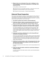
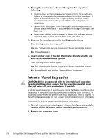
Is the problem a result of user error? Yes. Instruct the user in the proper procedure, or direct him or her to the appropriate user documentation for the correct procedure. No. Proceed to the next section, "External Visual Inspection." The external visual inspection consists of a quick inspection of the exterior of the computer, the monitor, the keyboard, any peripherals, and cables. While performing the visual inspection, make any necessary corrections. To perform the external visual inspection, follow these steps: For a PS/2-compatible mouse, the keyboard and mouse interface cable connectors are identical except for their labels. For a serial mouse, the mouse interface cable must be firmly attached to one of the serial port connectors, and its captive screws must be secure enough to ensure a firm connection. Each of the serial and parallel port interface cables must be firmly attached to an appropriate connector on the back of the computer as well as to the interface connector on the device. The captive screws that secure these connectors at each end of the interface cable must be secure enough to ensure a firm connection. For proper connection of the video monitor, see the documentation for the monitor. For proper settings of the video monitor controls, see the documentation for the monitor. 2-2
-
 1
1 -
2
-
3
-
4
-
5
-
6
-
7
-
8
-
9
-
10
-
11
-
12
-
13
-
14
-
15
-
16
-
17
-
18
-
19
-
20
-
21
-
22
-
23
-
24
-
25
-
26
-
27
-
28
-
29
-
30
-
31
-
32
-
33
-
34
-
35
-
36
-
37
-
38
-
39
-
40
-
41
-
42
-
43
-
44
-
45
-
46
-
47
-
48
-
 49
49 -
 50
50 -
 51
51 -
 52
52 -
 53
53 -
 54
54 -
 55
55 -
 56
56 -
 57
57 -
 58
58 -
 59
59 -
60
-
61
-
62
-
63
-
64
-
65
-
66
-
67
-
68
-
69
-
70
-
71
-
72
-
73
-
74
-
75
-
76
-
77
-
78
-
79
-
80
-
81
-
82
-
83
-
84
-
85
-
86
-
87
-
88
-
89
-
90
-
91
-
92
-
93
-
94
-
95
-
96
-
97
-
98
-
99
-
100
-
101
-
102
-
103
-
104
-
105
-
106
-
107
-
108
-
109
-
110
-
111
-
112
-
113
-
114
-
115
-
116
-
117
-
118
-
119
-
120
-
121
-
122
-
123
-
124
-
125
-
126
-
127
-
128
-
129
-
130
-
131
-
132
-
133
-
134
-
135
-
136
-
137
-
138
-
139
-
140
-
141
-
142
-
143
-
144
-
145
-
146
-
147
-
148
-
149
-
150
-
151
-
152
-
153
-
154
-
155
-
156
-
157
-
158
-
159
-
160
-
161
-
162
-
163
-
164
-
165
-
166
-
167
-
168
-
169
-
170
-
171
-
172
-
173
-
174
-
175
-
176
-
177
-
178
 |
 |