Dell OptiPlex NX1 Service Manual - Page 131
in the order stamped on the bottom of the 5.25-inch drive-mounting plate.
 |
View all Dell OptiPlex NX1 manuals
Add to My Manuals
Save this manual to your list of manuals |
Page 131 highlights
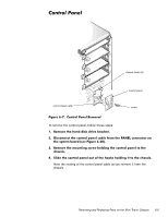
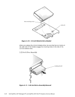
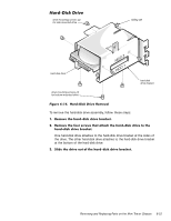
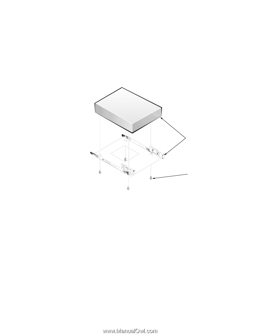
To remove a 5.25-inch drive assembly from the middle or lower drive bay, follow these steps: Align the front of the drive flush with the tab at the front of the 5.25-inch drive-mounting plate. screws (4) When you replace the 5.25-inch drive, align the front of the drive flush with the tab at the front of the mounting plate. Insert the four screws, and tighten them in the order stamped on the bottom of the 5.25-inch drive-mounting plate. Removing and Replacing Parts on the Mini Tower Chassis 6-13
-
 1
1 -
2
-
3
-
4
-
5
-
6
-
7
-
8
-
9
-
10
-
11
-
12
-
13
-
14
-
15
-
16
-
17
-
18
-
19
-
20
-
21
-
22
-
23
-
24
-
25
-
26
-
27
-
28
-
29
-
30
-
31
-
32
-
33
-
34
-
35
-
36
-
37
-
38
-
39
-
40
-
41
-
42
-
43
-
44
-
45
-
46
-
47
-
48
-
49
-
50
-
51
-
52
-
53
-
54
-
55
-
56
-
57
-
58
-
59
-
60
-
61
-
62
-
63
-
64
-
65
-
66
-
67
-
68
-
69
-
70
-
71
-
72
-
73
-
74
-
75
-
76
-
77
-
78
-
79
-
80
-
81
-
82
-
83
-
84
-
85
-
86
-
87
-
88
-
89
-
90
-
91
-
92
-
93
-
94
-
95
-
96
-
97
-
98
-
99
-
100
-
101
-
102
-
103
-
104
-
105
-
106
-
107
-
108
-
109
-
110
-
111
-
112
-
113
-
114
-
115
-
116
-
117
-
118
-
119
-
120
-
121
-
122
-
123
-
124
-
125
-
 126
126 -
 127
127 -
 128
128 -
 129
129 -
 130
130 -
 131
131 -
 132
132 -
 133
133 -
 134
134 -
 135
135 -
 136
136 -
137
-
138
-
139
-
140
-
141
-
142
-
143
-
144
-
145
-
146
-
147
-
148
-
149
-
150
-
151
-
152
-
153
-
154
-
155
-
156
-
157
-
158
-
159
-
160
-
161
-
162
-
163
-
164
-
165
-
166
-
167
-
168
-
169
-
170
-
171
-
172
-
173
-
174
-
175
-
176
-
177
-
178
 |
 |
Removing and Replacing Parts on the Mini Tower Chassis
6-13
To remove a 5.25-inch drive assembly from the middle or lower drive bay, fol-
low these steps:
¸³
’LVFRQQHFW²WKH²’&²SRZHU²FDEOH²DQG²WKH²LQWHUIDFH²FDEOH²IURP²WKH²
EDFN²RI²WKH²GULYH³
º³
3UHVV²LQ²RQ²WKH²WZR²UHWDLQLQJ²WDEV²·RQH²RQ²HDFK²VLGH²RI²WKH²GULYH½¶²
DQG²VOLGH²WKH²GULYH²DVVHPEO\²IRUZDUG²WR²UHPRYH²LW³²
»³
5HPRYH²WKH²IRXU²VFUHZV²DWWDFKLQJ²WKH²¹³º¹´LQFK²GULYH²WR²WKH²
PRXQWLQJ²SODWH¶²DQG²OLIW²WKH²GULYH²RXW²RI²WKH²PRXQWLQJ²SODWH²·VHH²
)LJXUH²¿´¸º½³
)LJXUH±¹´²µ³±±¸³µ¸´,QFK±’ULYH±5HPRYDO
When you replace the 5.25-inch drive, align the front of the drive flush with the
tab at the front of the mounting plate. Insert the four screws, and tighten them
in the order stamped on the bottom of the 5.25-inch drive-mounting plate.
Align the front of the drive
flush with the tab at the
front of the 5.25-inch
drive-mounting plate.
screws (4)