Dell OptiPlex NX1 Service Manual - Page 81
Check the alignment of the computer cover around the 5.25-inch drive bezel.
 |
View all Dell OptiPlex NX1 manuals
Add to My Manuals
Save this manual to your list of manuals |
Page 81 highlights
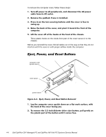
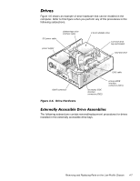
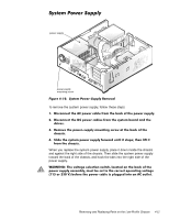
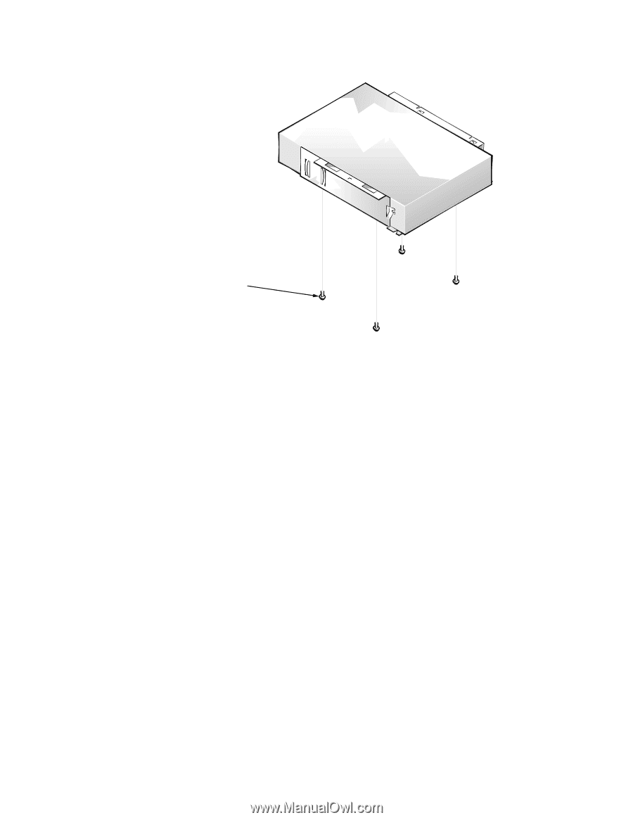
drive-mounting screws (4) front of computer To remove a 5.25-inch drive assembly, follow these steps: When you replace the 5.25-inch drive, place the front of the drive toward the front of the bracket; then install the four screws, but do not tighten them. Align the screws with the score marks on the bracket, and tighten the screws in the order stamped on the bottom of the bracket. Check the alignment of the computer cover around the 5.25-inch drive bezel. Adjust the drive forward or backward on the bracket to align it. Removing and Replacing Parts on the Low-Profile Chassis 4-9
-
 1
1 -
2
-
3
-
4
-
5
-
6
-
7
-
8
-
9
-
10
-
11
-
12
-
13
-
14
-
15
-
16
-
17
-
18
-
19
-
20
-
21
-
22
-
23
-
24
-
25
-
26
-
27
-
28
-
29
-
30
-
31
-
32
-
33
-
34
-
35
-
36
-
37
-
38
-
39
-
40
-
41
-
42
-
43
-
44
-
45
-
46
-
47
-
48
-
49
-
50
-
51
-
52
-
53
-
54
-
55
-
56
-
57
-
58
-
59
-
60
-
61
-
62
-
63
-
64
-
65
-
66
-
67
-
68
-
69
-
70
-
71
-
72
-
73
-
74
-
75
-
 76
76 -
 77
77 -
 78
78 -
 79
79 -
 80
80 -
 81
81 -
 82
82 -
 83
83 -
 84
84 -
 85
85 -
 86
86 -
87
-
88
-
89
-
90
-
91
-
92
-
93
-
94
-
95
-
96
-
97
-
98
-
99
-
100
-
101
-
102
-
103
-
104
-
105
-
106
-
107
-
108
-
109
-
110
-
111
-
112
-
113
-
114
-
115
-
116
-
117
-
118
-
119
-
120
-
121
-
122
-
123
-
124
-
125
-
126
-
127
-
128
-
129
-
130
-
131
-
132
-
133
-
134
-
135
-
136
-
137
-
138
-
139
-
140
-
141
-
142
-
143
-
144
-
145
-
146
-
147
-
148
-
149
-
150
-
151
-
152
-
153
-
154
-
155
-
156
-
157
-
158
-
159
-
160
-
161
-
162
-
163
-
164
-
165
-
166
-
167
-
168
-
169
-
170
-
171
-
172
-
173
-
174
-
175
-
176
-
177
-
178
 |
 |
Removing and Replacing Parts on the Low-Profile Chassis
4-9
¸·¹¸´,QFK±’ULYH±$VVHPEO\
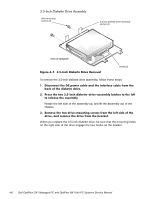
)LJXUH±·´À³±±¸³µ¸´,QFK±’ULYH±$VVHPEO\±5HPRYDO
To remove a 5.25-inch drive assembly, follow these steps:
¸³
5HPRYH²WKH²»³¹´LQFK²GLVNHWWH²GULYH²DVVHPEO\³
º³
’LVFRQQHFW²WKH²’&²SRZHU²FDEOH²DQG²WKH²LQWHUIDFH²FDEOH²IURP²WKH²
EDFN²RI²WKH²¹³º¹´LQFK²GULYH³
»³
/LIW²WKH²¹³º¹´LQFK²GULYH²DVVHPEO\²VWUDLJKW²XS²DQG²RXW²RI²WKH²
FKDVVLV³
¾³
/D\²WKH²¹³º¹´LQFK²GULYH²DVVHPEO\²XSVLGH²GRZQòWKHQ²UHPRYH²WKH²
IRXU²VFUHZV²DWWDFKLQJ²WKH²GULYH²WR²WKH²EUDFNHW³
When you replace the 5.25-inch drive, place the front of the drive toward the
front of the bracket; then install the four screws, but do not tighten them. Align
the screws with the score marks on the bracket, and tighten the screws in the
order stamped on the bottom of the bracket.
Check the alignment of the computer cover around the 5.25-inch drive bezel.
Adjust the drive forward or backward on the bracket to align it.
drive-mounting
screws (4)
front of computer