Dell OptiPlex NX1 Service Manual - Page 19
Reference and Installation Guide, work Administrator's Guide.
 |
View all Dell OptiPlex NX1 manuals
Add to My Manuals
Save this manual to your list of manuals |
Page 19 highlights
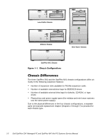
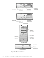
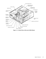
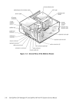
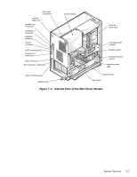
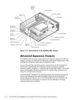
The computer's NIC connector (RJ45) is designed for attaching to an unshielded twisted pair (UTP) Ethernet cable. The other end of the cable connects to an RJ45 jack wall plate or to an RJ45 port on a UTP concentrator or hub, depending on the network configuration. Chapter 4, "Using Integrated Devices," in the Reference and Installation Guide provides instructions for connecting the computer to, and configuring it for use on, an Ethernet network. For OptiPlex NX1 systems, refer to the online Network Administrator's Guide. For desktop connectivity, the OptiPlex GX1 and OptiPlex NX1 systems include the following ports: 25-hole, bidirectional parallel port with EPP/ECP and demand-mode DMA support Two Universal Serial Bus (USB) ports Two 9-pin serial ports Two PS/2 ports (mouse and keyboard) One 15-hole video connector Three audio jacks (microphone, line-in, and line-out) One RJ45 Ethernet NIC connector See Figures 1-3 through 1-6 for I/O port identifiers for the various chassis configurations. The OptiPlex GX1 and OptiPlex NX1 systems are equipped with a switchselectable (115/230-VAC) UPS that can operate from standard AC power outlets in the U.S. and all international countries. The power supply used in the midsize and mini tower chassis configurations is a higher-capacity power supply than that used in the low-profile and OptiPlex NX1 chassis configurations. Dell OptiPlex GX1 and OptiPlex NX1 systems have a special power supply that provides trickle ("flea") power to support the Wakeup On LAN feature when computer power is off. Figure 1-2 shows the front-panel features for the four chassis types; Figures 1-3 through 1-6 show internal features of the four chassis types. System Overview 1-7
-
 1
1 -
2
-
3
-
4
-
5
-
6
-
7
-
8
-
9
-
10
-
11
-
12
-
13
-
 14
14 -
 15
15 -
 16
16 -
 17
17 -
 18
18 -
 19
19 -
 20
20 -
 21
21 -
 22
22 -
 23
23 -
 24
24 -
25
-
26
-
27
-
28
-
29
-
30
-
31
-
32
-
33
-
34
-
35
-
36
-
37
-
38
-
39
-
40
-
41
-
42
-
43
-
44
-
45
-
46
-
47
-
48
-
49
-
50
-
51
-
52
-
53
-
54
-
55
-
56
-
57
-
58
-
59
-
60
-
61
-
62
-
63
-
64
-
65
-
66
-
67
-
68
-
69
-
70
-
71
-
72
-
73
-
74
-
75
-
76
-
77
-
78
-
79
-
80
-
81
-
82
-
83
-
84
-
85
-
86
-
87
-
88
-
89
-
90
-
91
-
92
-
93
-
94
-
95
-
96
-
97
-
98
-
99
-
100
-
101
-
102
-
103
-
104
-
105
-
106
-
107
-
108
-
109
-
110
-
111
-
112
-
113
-
114
-
115
-
116
-
117
-
118
-
119
-
120
-
121
-
122
-
123
-
124
-
125
-
126
-
127
-
128
-
129
-
130
-
131
-
132
-
133
-
134
-
135
-
136
-
137
-
138
-
139
-
140
-
141
-
142
-
143
-
144
-
145
-
146
-
147
-
148
-
149
-
150
-
151
-
152
-
153
-
154
-
155
-
156
-
157
-
158
-
159
-
160
-
161
-
162
-
163
-
164
-
165
-
166
-
167
-
168
-
169
-
170
-
171
-
172
-
173
-
174
-
175
-
176
-
177
-
178
 |
 |