Dell OptiPlex NX1 Service Manual - Page 88
replacing system board components.
 |
View all Dell OptiPlex NX1 manuals
Add to My Manuals
Save this manual to your list of manuals |
Page 88 highlights
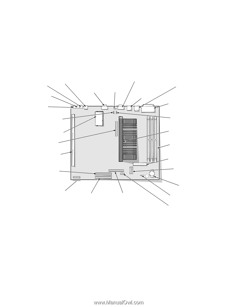
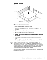
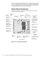
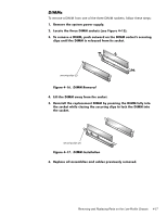
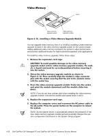
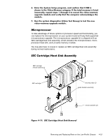
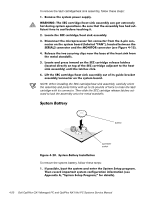
When you reinstall the system board (before you slide the system board back to lock it in position), push down near each slot to engage the grounding clip onto its corresponding tab. Push evenly on both sides of the system board as you slide it into position (do not twist the system board). The subsections that follow Figure 4-15 contain procedures for removing/ replacing system board components. microphone jack (MIC) line-out jack (LINE-OUT) optional NIC connector (ENET) video connector (MONITOR) line-in jack (LINE-IN) CD-ROM audio interface connector (CD_IN) video-memory upgrade socket (VIDEO_UPGRADE) ATI multimedia connector (AMC) riser board connector (RISER) secondary EIDE interface connector (IDE2) microprocessor fan connector (FAN) serial port 2 connector (SERIAL2) USB connectors (2) (USB) mouse/keyboard connectors (stacked) (MOUSE/KYBD) parallel/serial port 1 connectors (stacked) (PARALLEL/SERIAL1) telephony connector (TAPI) SEC cartridge connector (SLOT1) DIMM sockets (3) (DIMM_A-DIMM_C) main power input connector (POWER_1) 3.3-V power input connector (POWER_2) system board jumpers primary EIDE diskette/tape drive interface connector interface connector (IDE1) (DSKT) front of computer battery socket (BATTERY) chassis-intrusion switch connector (INTRUSION) control panel connector (PANEL) 4-16
-
 1
1 -
2
-
3
-
4
-
5
-
6
-
7
-
8
-
9
-
10
-
11
-
12
-
13
-
14
-
15
-
16
-
17
-
18
-
19
-
20
-
21
-
22
-
23
-
24
-
25
-
26
-
27
-
28
-
29
-
30
-
31
-
32
-
33
-
34
-
35
-
36
-
37
-
38
-
39
-
40
-
41
-
42
-
43
-
44
-
45
-
46
-
47
-
48
-
49
-
50
-
51
-
52
-
53
-
54
-
55
-
56
-
57
-
58
-
59
-
60
-
61
-
62
-
63
-
64
-
65
-
66
-
67
-
68
-
69
-
70
-
71
-
72
-
73
-
74
-
75
-
76
-
77
-
78
-
79
-
80
-
81
-
82
-
 83
83 -
 84
84 -
 85
85 -
 86
86 -
 87
87 -
 88
88 -
 89
89 -
 90
90 -
 91
91 -
 92
92 -
 93
93 -
94
-
95
-
96
-
97
-
98
-
99
-
100
-
101
-
102
-
103
-
104
-
105
-
106
-
107
-
108
-
109
-
110
-
111
-
112
-
113
-
114
-
115
-
116
-
117
-
118
-
119
-
120
-
121
-
122
-
123
-
124
-
125
-
126
-
127
-
128
-
129
-
130
-
131
-
132
-
133
-
134
-
135
-
136
-
137
-
138
-
139
-
140
-
141
-
142
-
143
-
144
-
145
-
146
-
147
-
148
-
149
-
150
-
151
-
152
-
153
-
154
-
155
-
156
-
157
-
158
-
159
-
160
-
161
-
162
-
163
-
164
-
165
-
166
-
167
-
168
-
169
-
170
-
171
-
172
-
173
-
174
-
175
-
176
-
177
-
178
 |
 |