Dell OptiPlex NX1 Service Manual - Page 79
Ulyhv
 |
View all Dell OptiPlex NX1 manuals
Add to My Manuals
Save this manual to your list of manuals |
Page 79 highlights
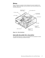
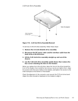
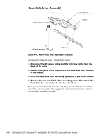
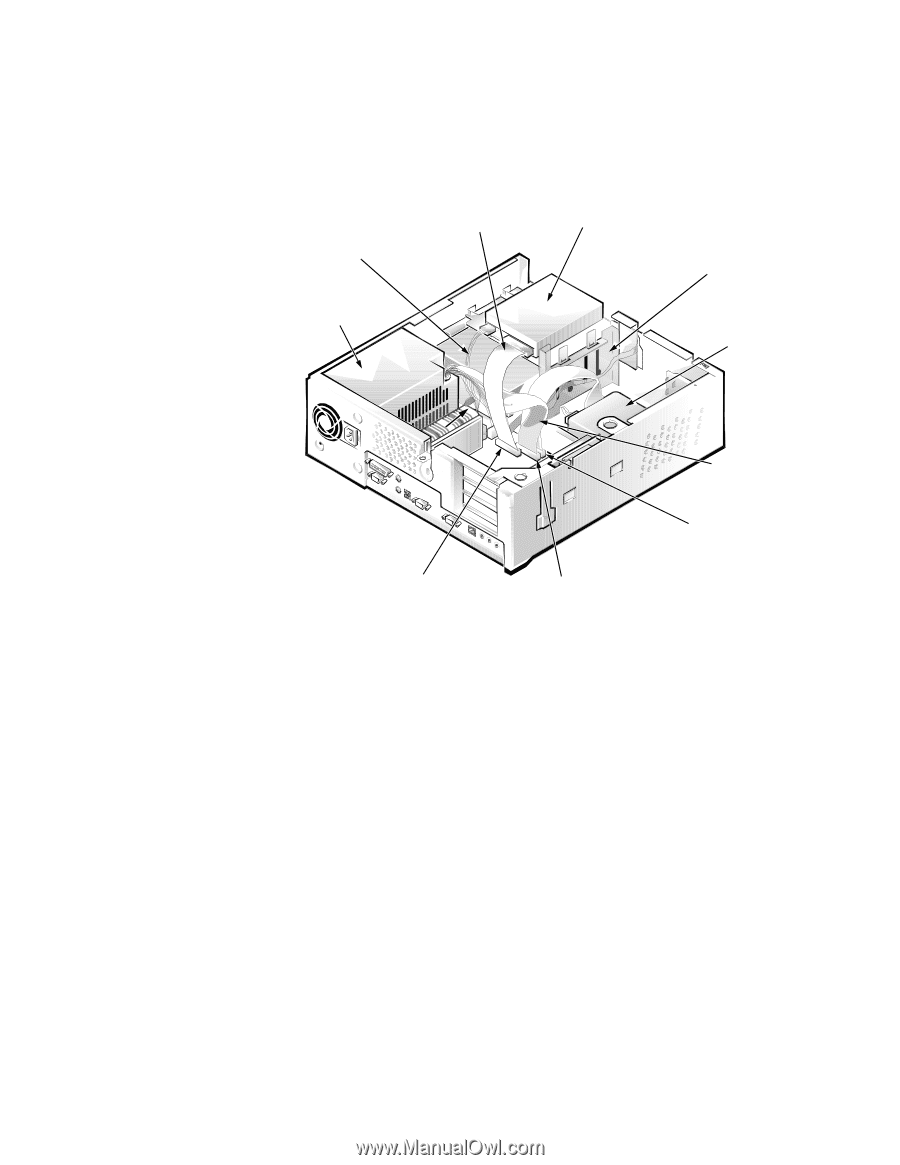
Figure 4-6 shows an example of drive hardware that can be installed in the computer. Refer to this figure when you perform any of the procedures in the following subsections. DC power cable diskette/tape drive interface cable power supply 3.5-inch diskette drive 5.25-inch drive bay and bracket hard-disk drive DSKT connector EIDE cable secondary EIDE interface connector (IDE2) primary EIDE interface connector (IDE1) The following subsections contain removal/replacement procedures for drives installed in the externally accessible drive bays. Removing and Replacing Parts on the Low-Profile Chassis 4-7
-
 1
1 -
2
-
3
-
4
-
5
-
6
-
7
-
8
-
9
-
10
-
11
-
12
-
13
-
14
-
15
-
16
-
17
-
18
-
19
-
20
-
21
-
22
-
23
-
24
-
25
-
26
-
27
-
28
-
29
-
30
-
31
-
32
-
33
-
34
-
35
-
36
-
37
-
38
-
39
-
40
-
41
-
42
-
43
-
44
-
45
-
46
-
47
-
48
-
49
-
50
-
51
-
52
-
53
-
54
-
55
-
56
-
57
-
58
-
59
-
60
-
61
-
62
-
63
-
64
-
65
-
66
-
67
-
68
-
69
-
70
-
71
-
72
-
73
-
 74
74 -
 75
75 -
 76
76 -
 77
77 -
 78
78 -
 79
79 -
 80
80 -
 81
81 -
 82
82 -
 83
83 -
 84
84 -
85
-
86
-
87
-
88
-
89
-
90
-
91
-
92
-
93
-
94
-
95
-
96
-
97
-
98
-
99
-
100
-
101
-
102
-
103
-
104
-
105
-
106
-
107
-
108
-
109
-
110
-
111
-
112
-
113
-
114
-
115
-
116
-
117
-
118
-
119
-
120
-
121
-
122
-
123
-
124
-
125
-
126
-
127
-
128
-
129
-
130
-
131
-
132
-
133
-
134
-
135
-
136
-
137
-
138
-
139
-
140
-
141
-
142
-
143
-
144
-
145
-
146
-
147
-
148
-
149
-
150
-
151
-
152
-
153
-
154
-
155
-
156
-
157
-
158
-
159
-
160
-
161
-
162
-
163
-
164
-
165
-
166
-
167
-
168
-
169
-
170
-
171
-
172
-
173
-
174
-
175
-
176
-
177
-
178
 |
 |
Removing and Replacing Parts on the Low-Profile Chassis
4-7
’ULYHV
Figure 4-6 shows an example of drive hardware that can be installed in the
computer. Refer to this figure when you perform any of the procedures in the
following subsections.
)LJXUH±·´¹³±±’ULYH±+DUGZDUH±
([WHUQDOO\±$FFHVVLEOH±’ULYH±$VVHPEOLHV
The following subsections contain removal/replacement procedures for drives
installed in the externally accessible drive bays.
EDFN
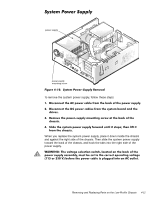
power supply
diskette/tape drive
interface cable
DC power cable
hard-disk drive
3.5-inch diskette drive
EIDE cable
DSKT connector
primary EIDE
interface
connector (IDE1)
secondary EIDE
interface
connector (IDE2)
5.25-inch drive
bay and bracket