Dell PowerEdge 1955 Configuration Guide
Dell PowerEdge 1955 Manual
 |
View all Dell PowerEdge 1955 manuals
Add to My Manuals
Save this manual to your list of manuals |
Dell PowerEdge 1955 manual content summary:
- Dell PowerEdge 1955 | Configuration Guide - Page 1
Dell™ PowerEdge™ 1955 Systems Configuration Guide Guide de configuration Konfigurationsanleitung Guía de configuración www.dell.com | support.dell.com - Dell PowerEdge 1955 | Configuration Guide - Page 2
- Dell PowerEdge 1955 | Configuration Guide - Page 3
Dell™ PowerEdge™ 1955 Systems Configuration Guide www.dell.com | support.dell.com - Dell PowerEdge 1955 | Configuration Guide - Page 4
in this document is subject to change without notice. © 2006 Dell Inc. All rights reserved. Reproduction in any manner whatsoever without the written permission of Dell Inc. is strictly forbidden. Trademarks used in this text: Dell, the DELL logo, PowerEdge, PowerConnect, and Dell OpenManage are - Dell PowerEdge 1955 | Configuration Guide - Page 5
1 General System Configuration 5 Other Documents You May Need 6 Initial Setup 7 Configuring Drive Mirroring 9 Additional Integrated Mirroring Guidelines 10 Connecting a USB Drive, Keyboard, and Mouse to the Server Module Front Panel 10 Installing an Operating System 10 Configuring the DRAC/MC - Dell PowerEdge 1955 | Configuration Guide - Page 6
Selecting Slots and Server Modules 36 Scanning Your System 37 Changing the Display Behavior 38 Setting Console Security 39 OSCAR Navigation Summary 42 Configuring and Using the Avocent Digital Access KVM Module 43 Configuring the Avocent Digital Access KVM Module Using the DRAC/MC 43 Using - Dell PowerEdge 1955 | Configuration Guide - Page 7
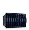
Front View 1 2 3 4 5 6 7 8 9 10 To function as a system, a server module is inserted into an enclosure that supports power supplies, fan modules, a management module (Dell™ Remote Access Controller/Modular Chassis [DRAC/MC]), a keyboard/video/mouse (KVM) switch module, and at least one I/O module - Dell PowerEdge 1955 | Configuration Guide - Page 8
• The Hardware Owner's Manual describes how to troubleshoot the system and install or replace system components. • The Dell Remote Access Controller/Modular Chassis User's Guide provides detailed information on using the remote management features of the system. • The Dell PowerEdge Expandable RAID - Dell PowerEdge 1955 | Configuration Guide - Page 9
for experienced users or technicians. Initial Setup 1 Unpack the system and install it in a rack. See the Getting Started Guide and Rack Installation Guide for more information. 2 Connect power to the power supplies. NOTE: You should power up the enclosure prior to inserting server modules if - Dell PowerEdge 1955 | Configuration Guide - Page 10
2 custom KVM cable 5 mouse 3 KVM module 6 keyboard 4 If required, configure the hard drives for RAID 1 or integrated mirroring. Configure RAID 1 prior to installation of the operating system. See "Configuring Drive Mirroring" on page 9 for more information. NOTE: If you ordered your server module - Dell PowerEdge 1955 | Configuration Guide - Page 11
8 and step 10 are not required unless you need to configure a static IP address. See the Dell Remote Access Controller/Modular Chassis User's Guide and the switch module's documentation for instructions on how to configure those modules for DHCP. 8 Configure the DRAC/MC module with an IP address - Dell PowerEdge 1955 | Configuration Guide - Page 12
before and after the operating system driver initialization. • Any replacement drives should be blank and not previously configured. • You should replace hard drives in an integrated-mirror configuration with drives of the same capacity. • After removing a hard drive in a hot-pluggable environment - Dell PowerEdge 1955 | Configuration Guide - Page 13
section includes general configuration information for the DRAC/MC module. For detailed information on configuring the DRAC/MC and using the remote management features of the DRAC/MC, see the Dell Remote Access Controller/Modular Chassis User's Guide. DRAC/MC Module Features The DRAC/MC provides - Dell PowerEdge 1955 | Configuration Guide - Page 14
connection with a null modem cable. DRAC/MC Configuration Interface Options You can configure the DRAC/MC and update DRAC/MC firmware using the following interfaces: • Web-based interface - Enables you to access the DRAC/MC using a supported Web browser through the DRAC/MC NIC. See "Web-Based - Dell PowerEdge 1955 | Configuration Guide - Page 15
, type your DRAC/MC user name and password. NOTE: The DRAC/MC default user name is root and the default password is calvin. For more information about using the DRAC/MC interface, see the online help or the Dell Remote Access Controller/Modular Chassis User's Guide. General System Configuration 13 - Dell PowerEdge 1955 | Configuration Guide - Page 16
Interface The DRAC/MC supports a serial and Telnet interface for its command line interface (CLI) and has the capability to switch this interface to any server module or switch module within the system enclosure.The following subsections provide information about how to enable and configure a serial - Dell PowerEdge 1955 | Configuration Guide - Page 17
Modem dialing and parameter settings Window size Required Setting 115200 8N1 Yes No ANSI Clear your user name and password. NOTE: If you are using Minicom for serial text console redirection to configure the DRAC/MC BIOS, it cable to the serial port on the DRAC/MC module and to the client system. - Dell PowerEdge 1955 | Configuration Guide - Page 18
tab, or use the cfgSerial object to configure the DRAC/MC using the RACADM CLI. For more information, see the Dell Remote Access Controller/Modular Chassis User's Guide. When running Telnet with Red Hat Enterprise Linux or SUSE Linux Enterprise Server, perform the following steps: NOTE: To ensure - Dell PowerEdge 1955 | Configuration Guide - Page 19
switch module inserted into the I/O bay is powered on automatically when the system enclosure is powered on. For more information on configuring the system enclosure using the DRAC/MC CLI interface, see the Dell Remote Access Controller/Modular Chassis User's Guide. General System Configuration 17 - Dell PowerEdge 1955 | Configuration Guide - Page 20
NOTE: You should power up the enclosure prior to inserting server modules if Ethernet switch modules are installed. The Ethernet switch may take longer to boot than the server modules, which may cause functions like PXE to fail due to the Ethernet switch not being fully booted and ready to send - Dell PowerEdge 1955 | Configuration Guide - Page 21
connection is successfully established and the switch module can be configured through the CLI. NOTE: The switch module's system indicator is off when the module is enabled and operating normally. If the switch has been disabled by the DRAC/MC, or there are hardware or firmware issues, the indicator - Dell PowerEdge 1955 | Configuration Guide - Page 22
to version 1.3 or later is not supported. NOTE: To facilitate the firmware upgrade, download a TFTP server from http://solarwinds.net. For information on installing and configuring the SolarWinds TFTP server, refer to the SolarWinds website. NOTICE: Since the DRAC/MC uses a different MAC address - Dell PowerEdge 1955 | Configuration Guide - Page 23
directly to version 1.3 or later is not supported. 1 If your system is configured with two DRAC/MC firmware version 1.0 modules, remove one DRAC/MC module from the system. 2 Copy the binary file mgmt.bin to a TFTP server root directory. 3 Log on to the DRAC/MC Telnet or serial interface. See "Using - Dell PowerEdge 1955 | Configuration Guide - Page 24
attach a null modem cable from the DRAC/MC serial port to your management station and run a terminal emulation software package to attach to the DRAC/MC. The console allows you to install the firmware through a TFTP server or through the DRAC/MC serial port. Integrating the System Into the Network - Dell PowerEdge 1955 | Configuration Guide - Page 25
2 Server module 10 LOM 1 LOM 2 I/O Bay 1 1/3 1/4 1/5 1/6 1/7 1/8 1/9 1/10 I/O Bay 2 1/3 1/4 1/5 1/6 1/7 1/8 1/9 1/10 Table 1-5. Uplink (External Ports) on Network Switch Network Switch 1 1/11 1/12 1/13 1/14 1/15 1/16 Network Switch 2 1/11 1/12 1/13 1/14 1/15 1/16 General System Configuration - Dell PowerEdge 1955 | Configuration Guide - Page 26
configure the uplink ports of the switch module in the same mode. For cabling, MDI ports connect to MDIX ports using straight-through twisted pair cabling cabling. Configuring a Port on a Dell PowerConnect 5316M Ethernet Switch Module The following is an example of how to configure to configure a - Dell PowerEdge 1955 | Configuration Guide - Page 27
Ethernet controller on the server modules and operate at 1000 Mb only. For additional information about the PowerConnect 5316M Ethernet switch module, see the documentation that shipped with the module or on support.dell.com. For detailed information on interoperability configurations, see the Link - Dell PowerEdge 1955 | Configuration Guide - Page 28
-through module is also available as an option and requires no configuration. The Gb Ethernet pass-through module must be connected to a 1000 Mb port on the external switch (10 Mb and 100 Mb ports are not supported). Before configuring the switch, obtain the following information from your network - Dell PowerEdge 1955 | Configuration Guide - Page 29
details on configuration procedures, see the Dell PowerConnect 5316M User's Guide. Updating the PowerConnect Switch Module Firmware This section contains instructions for downloading a new PowerConnect 5316M Ethernet switch module software system image through a TFTP server. The TFTP server must be - Dell PowerEdge 1955 | Configuration Guide - Page 30
To download a system image through the TFTP server: 1 Ensure that an IP address is configured on one of the Ethernet switch module ports and pings can be sent to a TFTP server. 2 Ensure that the file to be downloaded is saved on the TFTP server (the ros file). 3 Enter the show version command to - Dell PowerEdge 1955 | Configuration Guide - Page 31
-to-DB9 cable supplied with the module. • An internal serial management port provides access to the switch module through the DRAC/MC. For detailed information on the Cisco Catalyst Blade Switch 3030, see the documentation that shipped with the module or on support.dell.com. Before configuring the - Dell PowerEdge 1955 | Configuration Guide - Page 32
configure the Cisco Catalyst Blade Switch 3030 switch module using the DRAC/MC module, perform the following steps. 1 Log on to the DRAC/MC Telnet or serial interface. 2 To redirect the switch console through the DRAC to privileged EXEC mode: switch-1(config)# end 12 Verify the IP address: switch-1# - Dell PowerEdge 1955 | Configuration Guide - Page 33
card, press the key sequence during system boot to access the NIC configuration utility. For more information, see the Broadcom controller documentation on the documentation CD supplied with your system, or on the network controllers page on support.dell.com. NOTE: If PXE is enabled, the - Dell PowerEdge 1955 | Configuration Guide - Page 34
32 General System Configuration - Dell PowerEdge 1955 | Configuration Guide - Page 35
switch module (Figure 2-1) and Avocent Digital Access KVM switch module (Figure 2-2). NOTICE: The basic Dell™ KVM pass-though module used on the PowerEdge™ 1855 system is not supported by Dell PowerEdge 1955 server modules (blades). NOTE: The Avocent Analog KVM switch ACI port can only be used to - Dell PowerEdge 1955 | Configuration Guide - Page 36
the DRAC/MC" on page 43. • Connect a KVM cable (dongle) from the custom connector (seeFigure 1-3) to a local keyboard, monitor, and mouse. See "Configuring a KVM Using the OSCAR Interface and Direct Access" on page 35. • Connect a local KVM cable from the custom connector (seeFigure 2-2) to a Server - Dell PowerEdge 1955 | Configuration Guide - Page 37
configure an Analog KVM or Digital Access KVM switch module using direct access through a keyboard, monitor, and mouse, use the On-Screen Configuration and Reporting (OSCAR) graphical user dialog box. 4 Repeat steps 1-3 for each server module in the system. Configuring the KVM Switch Module 35 - Dell PowerEdge 1955 | Configuration Guide - Page 38
Table 2-1. OSCAR Status Symbols Symbol Description Server module is powered on Server module is powered off or not installed User connection Selecting Server Modules Use the Main dialog box to select server modules. When you select a server module, the KVM switch reconfigures the keyboard and mouse - Dell PowerEdge 1955 | Configuration Guide - Page 39
first few characters of the name of the server module and press . Scanning Your System In scan mode, the KVM switch automatically scans from slot to slot (server module to server module). You can scan up to 10 server modules by specifying which server modules you want to scan and the number - Dell PowerEdge 1955 | Configuration Guide - Page 40
Screen> to launch OSCAR. 2 Click Setup - Menu. To choose the display order of server modules in the Main dialog box: 1 Select Name to display server modules alphabetically by name. -orSelect Slot to display server modules numerically by slot number. 2 Click OK. 38 Configuring the KVM Switch Module - Dell PowerEdge 1955 | Configuration Guide - Page 41
to configure the flag to display by server module name, or to change the flag color, opacity, display time, and location on the desktop. To access the Flag dialog box: 1 Press . 2 Click Setup - Flag. Displaying Version Information Use the Version dialog box to display the KVM switch - Dell PowerEdge 1955 | Configuration Guide - Page 42
box. 2 Type the new password in the New text box and press . Passwords require 5 to 12 characters and must include at least one letter and one number. Passwords are stay connected to a server module before it automatically disengages you. 4 Click OK. 40 Configuring the KVM Switch Module - Dell PowerEdge 1955 | Configuration Guide - Page 43
saver mode with no password protection: 1 If your console does not require a password to gain access to the Security dialog box, go to OK. NOTE: Activation of the screen saver mode disconnects the server module. To exit the screen saver mode: Press any key or Configuring the KVM Switch Module 41 - Dell PowerEdge 1955 | Configuration Guide - Page 44
Single-click Enter Up/Down Arrows Right/Left Arrows Home/End Backspace Delete Numbers Caps Lock Function • Press once to open the Main dialog box, it closes OSCAR and returns to the selected server module. In a message box, it closes the pop-up box and case. 42 Configuring the KVM Switch Module - Dell PowerEdge 1955 | Configuration Guide - Page 45
the Avocent Digital Access KVM Module The Avocent Digital Access KVM switch module allows you to manage server modules and virtual media from a remote location. Configuring the Avocent Digital Access KVM Module Using the DRAC/MC 1 Open a supported Web browser. See "Supported Web Browsers" on page - Dell PowerEdge 1955 | Configuration Guide - Page 46
window. The procedure varies depending on the server module's operating system. See "Synchronizing the Mouse Pointers" in the Dell Remote Access Controller/Modular Chassis User's Guide for specific instructions for various supported operating systems. 44 Configuring the KVM Switch Module - Dell PowerEdge 1955 | Configuration Guide - Page 47
http:\\java.sun.com, download JRE 1.4.2 or later (1.4.x), and follow the instructions on screen. Virtual Media Dialog Box The Virtual Media dialog box allows you to connect a diskette device, a USB device, CD or DVD device to a target server. You can select one CD Drive device and one Mass Storage - Dell PowerEdge 1955 | Configuration Guide - Page 48
to the virtual drives. 3 Follow the steps for booting from the virtual media in the preceding section to ensure that the BIOS is set to boot from the CD drive that you are installing from. 4 Follow the instructions on the screen to complete the installation. 46 Configuring the KVM Switch Module - Dell PowerEdge 1955 | Configuration Guide - Page 49
can download a TFTP server from http://solarwinds.net. For information on installing and configuring the SolarWinds TFTP server, refer to the SolarWinds website. 1 Copy the KVM firmware binary file to a TFTP server root directory. 2 Log on to the DRAC/MC Web-based user interface using a supported - Dell PowerEdge 1955 | Configuration Guide - Page 50
Firmware NOTE: You can download a TFTP server from http://solarwinds.net. For information on installing and configuring the SolarWinds TFTP server, refer to the SolarWinds website. 1 Copy the KVM firmware binary file to a TFTP server root directory. 2 Log on to the DRAC/MC Telnet or serial interface - Dell PowerEdge 1955 | Configuration Guide - Page 51
Systèmes Dell™ PowerEdge™ 1955 Guide de configuration www.dell.com | support.dell.com - Dell PowerEdge 1955 | Configuration Guide - Page 52
. est strictement interdite. Marques utilisées dans ce document : Dell, le logo DELL, PowerEdge, PowerConnect et Dell OpenManage sont des marques de Dell Inc. ; Microsoft et Windows sont des marques déposées de Microsoft Corporation ; Windows Server est une marque de Microsoft Corporation ; SUSE est - Dell PowerEdge 1955 | Configuration Guide - Page 53
du système 53 Autres documents utiles 54 Configuration initiale 55 Configuration de la mise en DRAC/MC 68 Intégration du système au réseau 72 Mise à jour du micrologiciel pour le module commutateur PowerConnect 77 Configuration du commutateur Cisco Catalyst Blade Switch 3030 78 Configuration - Dell PowerEdge 1955 | Configuration Guide - Page 54
é sur la console 90 Récapitulatif des fonctions de navigation d'OSCAR 93 Configuration et utilisation du module KVM à accès numérique Avocent . . . 94 Configuration du module KVM à accès numérique Avocent via le module DRAC/MC 94 Utilisation de l'afficheur 95 Utilisation de médias virtuels 97 - Dell PowerEdge 1955 | Configuration Guide - Page 55
un châssis équipé de blocs d'alimentation, de modules de ventilation, d'un module de gestion DRAC/MC (Dell™ Remote Access Controller/Modular Chassis), d'un commutateur clavier/vidéo/souris (KVM) et d'au moins un module d'E-S pour la connectivité réseau (voir la figure 1-2). Les blocs d'alimentation - Dell PowerEdge 1955 | Configuration Guide - Page 56
réglementations. Les informations sur la garantie se trouvent soit dans ce document, soit à part. • Les documents Rack Installation Guide (Guide d'installation du rack) et Rack Installation Instructions (Instructions d'installation du rack) fournis avec la solution rack décrivent l'installation du - Dell PowerEdge 1955 | Configuration Guide - Page 57
Access Controller/Modular Chassis User's Guide (Guide d'utilisation du module DRAC/MC) contient des informations détaillées sur l'utilisation des fonctions de gestion à distance du système. • Le document Dell PowerEdge Expandable RAID Controller 5iR Integrated Mirroring Guide (Guide de mise en - Dell PowerEdge 1955 | Configuration Guide - Page 58
la souris au commutateur KVM. La figure 1-3 montre la configuration de câblage standard pour un commutateur KVM. Figure 1-3. Configuration de base d'un commutateur KVM 1 6 5 2 4 3 1 Moniteur 4 Module DRAC/MC 2 Câble modulable du commutateur KVM 5 Souris 3 Commutateur KVM 6 Clavier 4 Au besoin - Dell PowerEdge 1955 | Configuration Guide - Page 59
ne deviez définir une adresse IP statique. Consultez le document Dell Remote Access Controller/Modular Chassis User's Guide (Guide d'utilisation du module DRAC/MC) et la documentation du module commutateur pour obtenir des instructions sur la configuration DHCP de ces modules. 8 Configurez le module - Dell PowerEdge 1955 | Configuration Guide - Page 60
document Dell SAS 5/iR Integrated and Adapter User's Guide (Guide d'utilisation des cartes Dell SAS 5/iR standard et intégrée). 1 Lors de l'auto-test de démarrage, appuyez sur pour ouvrir l'utilitaire de configuration équipés d'aucun support amovible. • Un disque virtuel configuré en RAID 1 - Dell PowerEdge 1955 | Configuration Guide - Page 61
, de CD-ROM ou configuration du module DRAC/MC. Pour plus d'informations sur la configuration de ce module et l'utilisation de ses fonctions de gestion à distance, consultez le document Dell Remote Access Controller/Modular Chassis User's Guide (Guide d'utilisation du module DRAC/MC). Configuration - Dell PowerEdge 1955 | Configuration Guide - Page 62
informations sur la mise à jour du micrologiciel. Figure 1-4. Caractéristiques du module DRAC/MC 1 2 3 5 4 M S 1 Voyant d'activité 4 Voyant de panne 2 Voyant de lien 5 Connecteur série 3 Voyant principal/attente (modules DRAC/MC redondants uniquement) 60 Configuration générale du système - Dell PowerEdge 1955 | Configuration Guide - Page 63
redondante. Utilisée pour une connexion série via un câble simulateur de modem. Options de l'interface de configuration du module DRAC/MC Pour configurer un module DRAC/MC ou mettre à jour son micrologiciel, vous pouvez utiliser les interfaces suivantes : • Interface Web : permet d'utiliser - Dell PowerEdge 1955 | Configuration Guide - Page 64
par défaut est root, mot de passe calvin. Pour plus d'informations sur l'utilisation de l'interface du module DRAC/MC, consultez l'aide en ligne ou le document Dell Remote Access Controller/Modular Chassis User's Guide (Guide d'utilisation du module DRAC/MC). 62 Configuration générale du système - Dell PowerEdge 1955 | Configuration Guide - Page 65
message suivant : = System Setup 3 Faites défiler la liste ou VT100/VT200. Redirection After Boot (Redirection après démarrage) configuration du module serveur. Connexion au module DRAC/MC via Minicom pour l'émulation de la console série (Red Hat Enterprise Linux et SUSE Linux Enterprise Server - Dell PowerEdge 1955 | Configuration Guide - Page 66
votre nom d'utilisateur et votre mot de passe. REMARQUE : si vous utilisez Minicom pour rediriger la console texte série afin de configurer le BIOS du module DRAC/MC, il est recommandé d'activer les couleurs. Pour ce faire, tapez minicom -c on dans l'invite shell. Voir "Utilisation d'une console - Dell PowerEdge 1955 | Configuration Guide - Page 67
configurer le module DRAC/MC via l'interface CLI de RACADM. Pour plus d'informations, consultez le document Dell Remote Access Controller/Modular Chassis User's Guide (Guide d'utilisation du module DRAC/MC). Lorsque vous exécutez Telnet sous Red Hat Enterprise Linux ou SUSE Linux Enterprise Server - Dell PowerEdge 1955 | Configuration Guide - Page 68
les commandes CLI de RACADM. Pour plus d'informations, voir "Using the DRAC/MC CLI Commands" (Utilisation des commandes CLI du module DRAC/MC), dans le manuel Dell Remote Access Controller/Modular Chassis User's Guide (Guide d'utilisation du module DRAC/MC). 1 Cliquez sur OK. L'application du module - Dell PowerEdge 1955 | Configuration Guide - Page 69
la baie d'E-S. Pour plus d'informations sur la configuration du châssis du système à l'aide de l'interface CLI du module DRAC/MC, consultez le document Dell Remote Access Controller/Modular Chassis User's Guide (Guide d'utilisation du module DRAC/MC). REMARQUE : si des modules commutateurs Ethernet - Dell PowerEdge 1955 | Configuration Guide - Page 70
connexion est opérationnelle et que le module commutateur peut être configuré via l'interface CLI. REMARQUE : lorsque le module commutateur est sous 69. • Interface CLI de RACADM : voir "Mise à jour du micrologiciel du module DRAC/MC via l'interface CLI de RACADM", à la page 70. • Console de récupé - Dell PowerEdge 1955 | Configuration Guide - Page 71
un serveur TFTP à partir du site http://solarwinds.net. Pour plus d'informations sur l'installation et la configuration du serveur SolarWinds TFTP, consultez le site Web de SolarWinds. AVIS : le module DRAC/MC utilisant une adresse MAC différente pendant la mise à jour du micrologiciel, il envoie un - Dell PowerEdge 1955 | Configuration Guide - Page 72
même image binaire. Si vous effectuez la mise à niveau à partir de la version 1.0, procédez comme suit : a Retirez le module DRAC/MC mis à jour du système. b Insérez le second module DRAC/MC dans le système. c Recommencez la procédure, de l'étape 3 à l'étape 5. 70 Configuration générale du système - Dell PowerEdge 1955 | Configuration Guide - Page 73
Clear Disk Cache (Vider la mémoire cache du disque). 4 Sélectionnez Clear Memory Cache (Vider la mémoire cache). 5 Cliquez sur OK. 6 Fermez le au module DRAC/MC. Cette console permet d'installer le micrologiciel via un serveur TFTP ou via le port série du module DRAC/MC. Configuration générale - Dell PowerEdge 1955 | Configuration Guide - Page 74
serveur 6 LOM 1 LOM 2 Module serveur 7 LOM 1 LOM 2 Module serveur 8 LOM 1 LOM 2 Module serveur 9 LOM 1 LOM 2 Module serveur 10 LOM 1 LOM 2 Baie d'E-S 1 1/1 1/2 1/3 1/4 1/5 1/6 1/7 1/8 1/9 1/10 Baie d'E-S 2 1/1 1/2 1/3 1/4 1/5 1/6 1/7 1/8 1/9 1/10 72 Configuration générale du système - Dell PowerEdge 1955 | Configuration Guide - Page 75
le module de commutation réseau aux périphériques réseau externes (commutateurs, routeurs ou NIC). Si les ports sortants du périphérique réseau externe sont configurés en mode forcé (100 Mbps ou 1000 Mbps en duplex intégral, par exemple), configurez ceux du module commutateur de la même façon. Pour - Dell PowerEdge 1955 | Configuration Guide - Page 76
Cisco Catalyst Blade Switch 3030 L'exemple suivant indique comment configurer un port pour un fonctionnement à 100 Mbps et en mode semi duplex. (Au lieu d'utiliser le port de console externe situé sur le module commutateur, vous pouvez configurer ce dernier à l'aide du module DRAC/MC.) 1 Connectez - Dell PowerEdge 1955 | Configuration Guide - Page 77
PowerConnect 5316M, consultez la documentation fournie avec celui-ci ou disponible sur le site support.dell.com. Pour obtenir des IP de la passerelle par défaut Pour configurer le module commutateur Ethernet PowerConnect 5316M à l'aide du port série interne du module DRAC/MC, procédez comme suit : 1 - Dell PowerEdge 1955 | Configuration Guide - Page 78
)# snmp-server community private configuration en cours (conservée dans la RAM) à chaque démarrage du module. Pour plus d'informations sur les procédures de configuration, consultez le document Dell PowerConnect 5316M User's Guide (Guide d'utilisation du Dell PowerConnect 5316M). 76 Configuration - Dell PowerEdge 1955 | Configuration Guide - Page 79
copie de l'image système. Au démarrage suivant, le module commutateur Ethernet décompresse et exécute l'image système en cours, sauf si l'utilisateur a configuré les paramètres de démarrage différemment. Pour télécharger une image système via le serveur TFTP : 1 Assurez-vous qu'une adresse IP est - Dell PowerEdge 1955 | Configuration Guide - Page 80
éder au module commutateur via le module DRAC/MC. Pour plus d'informations sur le commutateur Cisco Catalyst Blade Switch 3030, consultez la documentation fournie avec celui-ci ou disponible sur le site support.dell.com. Avant de configurer le commutateur, demandez les informations suivantes à votre - Dell PowerEdge 1955 | Configuration Guide - Page 81
du commutateur. 4 Cliquez sur Submit (Soumettre) pour actualiser la configuration du commutateur. Configuration du commutateur à l'aide d'une console série ou Telnet Pour configurer le commutateur Cisco Catalyst Blade Switch 3030 à l'aide du module DRAC/MC, procédez comme suit : 1 Connectez-vous - Dell PowerEdge 1955 | Configuration Guide - Page 82
)# ip address adresse-IP masque-sous-réseau 9 Revenez au mode Global Configuration : switch-1(config-vlan)# exit 10 Indiquez l'adresse IP de la passerelle -gateway adresse IP 11 Revenez au mode Privileged EXEC: switch-1(config)# end 12 Vérifiez l'adresse IP : switch-1# show interfaces vlan ID du - Dell PowerEdge 1955 | Configuration Guide - Page 83
PRO Gigabit proposés sur le site support.dell.com. Suivez les instructions fournies par l'utilitaire. REMARQUE : configuration du NIC. Pour plus d'informations, consultez la documentation du contrôleur Broadcom. Elle est disponible sur le CD fourni avec le système, ainsi que sur le site support.dell - Dell PowerEdge 1955 | Configuration Guide - Page 84
82 Configuration générale du système - Dell PowerEdge 1955 | Configuration Guide - Page 85
la configuration des deux commutateurs KVM Avocent pris en charge par le système : module analogique (figure 2-1) et module numérique (figure 2-2). AVIS : le module KVM Dell™ de base utilisé sur les systèmes PowerEdge™ 1855 n'est pas pris en charge par les modules serveurs Dell PowerEdge 1955 (lames - Dell PowerEdge 1955 | Configuration Guide - Page 86
pour relier le connecteur modulable (voir la figure 2-2) à un SIP (Server Interface Pod). Utilisez ensuite un câble CAT 5 pour relier le SIP à un commutateur KVM Dell externe, analogique ou numérique. Voir "Configuration d'un module KVM par accès direct via l'interface OSCAR", à la page 85. 84 - Dell PowerEdge 1955 | Configuration Guide - Page 87
). La boîte de dialogue Main (Écran principal) s'affiche. 2 Cliquez sur Setup - Names (Configuration - Noms). REMARQUE : si de nouveaux modules serveurs sont détectés par le système de commutation KVM, la liste affichée est mise à jour automatiquement. Le curseur de la souris prend la forme - Dell PowerEdge 1955 | Configuration Guide - Page 88
la signification des symboles d'état. Tableau 2-1. Symboles d'état OSCAR Symbole Description Module serveur sous tension Module serveur hors tension ou non installé Connexion utilisateur 86 Configuration du commutateur KVM - Dell PowerEdge 1955 | Configuration Guide - Page 89
pas. 1 Appuyez sur pour lancer l'interface OSCAR. 2 Cliquez sur Setup - Menu (Configuration - Menu). 3 Sélectionnez Name (Nom) ou Slot (Emplacement) pour Display/Sort Key (Critère d'affichage ères lettres du nom du module et appuyez sur . Configuration du commutateur KVM 87 - Dell PowerEdge 1955 | Configuration Guide - Page 90
1 Si OSCAR n'est pas ouvert, appuyez sur . 2 Cliquez sur Setup - Scan (Configuration - Analyse). 3 La boîte de dialogue qui s'affiche contient la liste de tous les modules serveurs (Activer l'analyse) dans la boîte de dialogue Command (Commande). 88 Configuration du commutateur KVM - Dell PowerEdge 1955 | Configuration Guide - Page 91
sur pour lancer l'interface OSCAR. 2 Cliquez sur Setup - Menu (Configuration - Menu). Pour définir l'ordre de tri des modules serveurs dans la boîte de fonctions de commutation logicielle. Voir la section "Configuration de l'interface OSCAR pour la commutation logicielle" pour plus de - Dell PowerEdge 1955 | Configuration Guide - Page 92
versions La boîte de dialogue Version permet d'afficher différentes informations : version de micrologiciel du commutateur KVM, versions du matériel et FPGA, langue et configuration du clavier. Pour obtenir un niveau de performances optimales, installez les mises à jour du micrologiciel dès qu'elles - Dell PowerEdge 1955 | Configuration Guide - Page 93
suit : 1 Dans la boîte de dialogue Main (Écran principal), cliquez sur Setup - Security (Configuration - Sécurité). 2 Saisissez le mot de passe, puis cliquez sur OK. La boîte de dialogue doit rester active avant déconnexion automatique. 4 Cliquez sur OK. Configuration du commutateur KVM 91 - Dell PowerEdge 1955 | Configuration Guide - Page 94
dez comme suit : 1 Dans la boîte de dialogue Main (Écran principal), cliquez sur Setup - Security (Configuration - Sécurité). 2 Saisissez le mot de passe, puis cliquez sur OK. 3 Dans la boîte de être sélectionnée dans la boîte de dialogue Security (Sécurité). 92 Configuration du commutateur KVM - Dell PowerEdge 1955 | Configuration Guide - Page 95
combinaison de touches avant la fin de ce délai, l'interface OSCAR ne s'affiche pas. Voir "Configuration de l'interface OSCAR pour la commutation logicielle", à la page 87. Affiche l'écran Help (Aide) Désactivé. Utilisez la touche pour changer de casse. Configuration du commutateur KVM 93 - Dell PowerEdge 1955 | Configuration Guide - Page 96
modules serveurs et des médias virtuels. Configuration du module KVM à accès numérique Avocent via le module DRAC/MC 1 Ouvrez un navigateur Web pris en par défaut : Off (Désactivé) Permet à Dell OpenManage™ d'obtenir l'adresse IP du NIC du module KVM à accès numérique Avocent à partir du serveur - Dell PowerEdge 1955 | Configuration Guide - Page 97
navigateur Web, tapez https:// où correspond à l'adresse IP du module DRAC/MC. REMARQUE : l'adresse IP par défaut du module est 192.168.0.120. 2 Cliquez sur DRAC/MC dans la partie gauche de l'interface pour ouvrir le menu correspondant. Configuration du commutateur KVM 95 - Dell PowerEdge 1955 | Configuration Guide - Page 98
de souris), dans le document Dell Remote Access Controller/Modular Chassis User's Guide (Guide d'utilisation du module DRAC/MC) pour obtenir les instructions adaptées aux différents à une désynchronisation vidéo, cliquez sur Refresh (Rafraîchir) dans l'afficheur. 96 Configuration du commutateur KVM - Dell PowerEdge 1955 | Configuration Guide - Page 99
suivez les instructions qui s' Drive (Lecteur de disquette) ou CD/DVD Drive (Lecteur de CD/DVD), sélectionnez le média virtuel à connecter au périphérique. 7 Cliquez sur Browse (Parcourir) et sélectionnez le lecteur approprié. 8 Cliquez sur Connect (Connecter). Configuration du commutateur KVM - Dell PowerEdge 1955 | Configuration Guide - Page 100
virtuel tel qu'un lecteur de CD/DVD, vous devrez peut-être modifier l'option Boot Sequence (Séquence d'amorçage) dans le programme de configuration du système. Voir "Utilisation du programme de configuration du système", dans le document Hardware Owner's Manual (Manuel du propriétaire) pour plus - Dell PowerEdge 1955 | Configuration Guide - Page 101
de RACADM Mise à jour du micrologiciel du commutateur KVM via l'interface Web du module DRAC/MC REMARQUE : vous pouvez télécharger un serveur TFTP à partir du site http://solarwinds.net. Pour plus d'informations sur l'installation et la configuration du serveur SolarWinds TFTP, consultez le site Web - Dell PowerEdge 1955 | Configuration Guide - Page 102
configuration du serveur SolarWinds TFTP, consultez le site Web de SolarWinds. 1 Copiez le fichier binaire contenant le micrologiciel du commutateur KVM dans le répertoire racine d'un serveur TFTP. 2 Connectez-vous à l'interface Telnet ou série du module DRAC/MC. Voir - Dell PowerEdge 1955 | Configuration Guide - Page 103
Dell™ PowerEdge™ 1955-Systeme Konfigurationsanleitung www.dell.com | support.dell.com - Dell PowerEdge 1955 | Configuration Guide - Page 104
und zeigt auf, wie derartige Probleme vermieden werden können. VORSICHT: Hiermit Dell Inc. streng untersagt. Marken in diesem Text: Dell, das DELL Logo, PowerEdge, PowerConnect und Dell OpenManage sind Marken von Dell Inc.; Microsoft und Windows sind eingetragene Marken und Windows Server - Dell PowerEdge 1955 | Configuration Guide - Page 105
-Konsole auf das Ethernet-Switchmodul 121 Aktualisieren der DRAC/MC-Firmware 121 Integration des Systems im Netzwerk 125 Aktualisieren der PowerConnect Switchmodul-Firmware 130 Konfiguration des Cisco Catalyst Blade-Switches 3030 131 Konfiguration des Cisco-Switches mit einem Browser und einer - Dell PowerEdge 1955 | Configuration Guide - Page 106
Konsolensicherheitsfunktionen 142 OSCAR-Navigationsübersicht 145 Konfiguration und Verwendung des Avocent Digital Access KVM-Moduls 146 Konfiguration des Avocent Digital Access KVM-Modul über das DRAC/MC-Modul 146 Verwenden der Videoanzeige 147 Verwenden von virtuellen Medien 149 Aktualisieren - Dell PowerEdge 1955 | Configuration Guide - Page 107
sein. Abbildung 1-1. Vorderansicht des Systems 1 2 3 4 5 6 7 8 9 10 Servermodule werden für den Systembetrieb in ein Gehäuse eingesetzt, das Netzteile, Lüftermodule, ein DRAC/MC-Verwaltungsmodul (Dell™ Remote Access Controller/Modular Chassis), ein KVM-Switchmodul (für Tastatur, Bildschirm und - Dell PowerEdge 1955 | Configuration Guide - Page 108
Rack Installation Instructions (Rack-Installationsanleitung) ist beschrieben, wie das System in einem Rack installiert wird. • Im Dokument Getting Started Guide (Erste Schritte) finden Sie eine Übersicht über die Ersteinrichtung des Systems. • Im Hardware Owner's Manual (Hardware-Benutzerhandbuch - Dell PowerEdge 1955 | Configuration Guide - Page 109
Dell Remote Access Controller/Modular Chassis User's Guide (Benutzerhandbuch zum Dell Remote Access Controller/Modular Chassis) enthält ausführliche Informationen zum Einsatz der Fernverwaltungsfunktionen des Systems. • In der Dell PowerEdge Expandable RAID Controller 5iR Integrated Mirroring Guide - Dell PowerEdge 1955 | Configuration Guide - Page 110
, den Bildschirm und die Maus mit dem KVM-Modul. Abbildung 1-3 zeigt die grundlegende Verkabelung für ein KVM-Modul. Abbildung 1-3. Grundlegende KVM-Verkabelung 1 6 5 2 4 3 1 Bildschirm 4 DRAC/MC-Modul 2 KVM-Adapterkabel 5 Maus 3 KVM-Modul 6 Tastatur 4 Konfigurieren Sie gegebenenfalls die - Dell PowerEdge 1955 | Configuration Guide - Page 111
119. Weitere Konfigurationsoptionen sind im Dell Remote Access Controller/Modular Chassis User's Guide (Benutzerhandbuch zum Dell Remote Access Controller/Modular Chassis) beschrieben. 9 Falls erforderlich, setzen Sie die serielle Konsole mit der DRAC/MC-Befehlszeilenschnittstelle (CLI) auf die - Dell PowerEdge 1955 | Configuration Guide - Page 112
Anweisungen vorgehen oder die mitgelieferte Arrayverwaltungssoftware verwenden. Ausführliche Informationen erhalten Sie im Dell SAS 5/iR Integrated and Adapter User's Guide (Benutzerhandbuch zum Dell SAS 5/iR-Integrated und -Adapter). 1 Drücken Sie während des Einschaltselbsttests (POST - Dell PowerEdge 1955 | Configuration Guide - Page 113
Sie ein USB-Laufwerk (DVD-ROM, CD-ROM oder Diskette), eine USB-Tastatur DRAC/MC-Moduls und die Verwendung der Fernverwaltungsfunktionen des DRAC/MC-Moduls, erhalten Sie im Dell Remote Access Controller/Modular Chassis User's Guide (Benutzerhandbuch zum Dell Remote Access Controller/Modular Chassis - Dell PowerEdge 1955 | Configuration Guide - Page 114
muss über die Firmwareversion 1.3 oder höher verfügen. HINWEIS: Zur Unterstützung von redundantem DRAC/MC-Betrieb müssen beide Module über die Firmwareversion 1.3 oder höher verfügen. Das Kombinieren von zwei DRAC/MC-Modulen mit Firmwareversionen älter als 1.3 kann dazu führen, dass das Gehäuse die - Dell PowerEdge 1955 | Configuration Guide - Page 115
. Das LAN ist verbunden. Aktivitätsanzeige für Netzwerkcontroller Aus Keine aktive Kommunikation mit dem LAN. Gelb blinkend Zeigt an, dass das DRAC/MC-Modul mit dem LAN kommuniziert. Anzeige für Primär/Standby Fehleranzeige Serieller Anschluss Aus Grün Grün blinkend Aus Gelb Gelb blinkend - Dell PowerEdge 1955 | Configuration Guide - Page 116
, und das Standardkennwort ist calvin. Weitere Informationen über die DRAC/MC-Schnittstelle erhalten Sie in der Onlinehilfe oder im Dell Remote Access Controller/Modular Chassis User's Guide (Benutzerhandbuch zum Dell Remote Access Controller/Modular Chassis). 114 Allgemeine Systemkonfiguration - Dell PowerEdge 1955 | Configuration Guide - Page 117
Type - ANSI oder VT100/VT200. Redirection After Boot - Enabled ANMERKUNG: Wenn sich das Terminal Sie , um das System-Setup-Programm des Servermoduls zu beenden. Verbindung mit dem DRAC/MC-Modul über Minicom Enterprise Linux und SUSE Linux Enterprise Server. ANMERKUNG: Um die korrekte Textanzeige - Dell PowerEdge 1955 | Configuration Guide - Page 118
: Wenn Sie Minicom zur seriellen Konsolenumleitung verwenden, um das BIOS des DRAC/MC-Moduls zu konfigurieren, ist eventuell das Aktivieren der Farbdarstellung Sie das Nullmodemkabel mit der seriellen Schnittstelle am DRAC/MC-Modul und mit dem Client-System. 2 Klicken Sie auf die Schaltfläche Start - Dell PowerEdge 1955 | Configuration Guide - Page 119
die Registerkarte Configuration (Konfiguration) der webbasierten Benutzerschnittstelle oder das cfgSerial-Objekt, um das DRAC/MC-Modul mit der RACADM-CLI zu konfigurieren. Weitere Informationen finden Sie im Dell Remote Access Controller/Modular Chassis User's Guide (Benutzerhandbuch zum Dell Remote - Dell PowerEdge 1955 | Configuration Guide - Page 120
Xterm-Fenster statt des Standardfensters von Red Hat Enterprise Linux und SUSE Linux Enterprise Server. 1 Verbinden Sie das Nullmodemkabel mit der seriellen Schnittstelle am DRAC/MC-Modul und mit dem Client-System. 2 Um eine neue Xterm-Sitzung zu starten, geben Sie xterm & an der Eingabeaufforderung - Dell PowerEdge 1955 | Configuration Guide - Page 121
oder Telnet-Konsole eingeben. Weitere Informationen erhalten Sie im Dell Remote Access Controller/Modular Chassis User's Guide (Benutzerhandbuch zum Dell Remote Access Controller/Modular Chassis) unter „Using the DRAC/MC CLI Commands" (Verwenden der DRAC/MC-CLI-Befehle). 1 Klicken Sie auf OK. Die - Dell PowerEdge 1955 | Configuration Guide - Page 122
4 Geben Sie zum Einstellen der DRAC/MC-Uhrzeit Folgendes ein: racadm setractime -d yyyymmddhhmmss.mmmmmmsoff Hierfür gilt: - yyyy ist eine 4-stellige Jahresangabe - mm ist der Monat - dd ist der Tag - hh ist die Stunde (im 24-Stunden-System) - mm ist die Minute - ss ist die Sekunde - mmmmmm ist die - Dell PowerEdge 1955 | Configuration Guide - Page 123
und ordnungsgemäß funktioniert. Wenn der Switch vom DRAC/MC deaktiviert wurde oder Probleme mit der Hardware oder Firmware bestehen, leuchtet den Firmware-Upgrade zu vereinfachen, laden Sie einen TFTP-Server von http://solarwinds.net herunter. Informationen über die Installation und Konfiguration des - Dell PowerEdge 1955 | Configuration Guide - Page 124
werden. Um dieses Problem zu vermeiden, deaktivieren Sie das Spanning Tree Protocol an den Switch-Ports, die mit allen DRAC/MCModulen während vor: a Entfernen Sie das aktualisierte DRAC/MC-Modul aus dem System. b Setzen Sie das verbleibende DRAC/MC-Modul im System ein. c Wiederholen Sie Schritt 2 - Dell PowerEdge 1955 | Configuration Guide - Page 125
oder höher wird nicht unterstützt. 1 Wenn das System mit zwei DRAC/MC-Modulen mit der Firmwareversion 1.0 ausgestattet ist, entfernen Sie ein DRAC/MC-Modul aus dem System. 2 Kopieren Sie die Binärdatei mgmt.bin in ein Stammverzeichnis des TFTP-Servers. 3 Melden Sie sich an der seriellen oder Telnet - Dell PowerEdge 1955 | Configuration Guide - Page 126
löschen). 4 Wählen Sie Clear Memory Cache (Cache im Hauptspeicher löschen). DRAC/MC-Schnittstelle mit der Verwaltungsstation, und verbinden Sie sich mit einer Terminal-Emulationssoftware mit dem DRAC/MC-Modul. In der Konsole können Sie die Firmware über einen TFTP-Server oder über die serielle DRAC - Dell PowerEdge 1955 | Configuration Guide - Page 127
Integration des Systems im Netzwerk Das System im Wesentlichen ein geschlossenes Netzwerk. Tabelle 1-8, Tabelle 1-9 und Tabelle 1-10 zeigen die Zuweisung der internen und externen Ports. Tabelle 1-4. Interne Netzwerk-Port-Zuweisung Modul-Port - Dell PowerEdge 1955 | Configuration Guide - Page 128
Tabelle 1-5. Uplink-Ports (externe Ports) am Netzwerk-Switch Netzwerk-Switch 1 1/11 1/12 1/13 1/14 1/15 1/16 Netzwerk-Switch 2 1/11 1/12 1/13 1/14 1/15 1/16 Tabelle 1-6. Uplink- oder externe Ports am Gb-Ethernet-Passthrough-Modul (PHY-Modul) Gb-EthernetPassthrough 1 1/1 1/2 1/3 1/4 1/5 1/6 1/7 - Dell PowerEdge 1955 | Configuration Guide - Page 129
Dell bei einem Cisco Catalyst Blade Switch 3030-Switchmodul Das DRAC/MC-Benutzerschnittstelle an. 2 Geben Sie den folgenden Befehl ein, um in die privilegierte EXEC-Betriebsart zu gelangen: switch-1> enable 3 Wechseln Sie in die globale Konfigurationsbetriebsart: switch-1# configure if)# end 8 Beenden - Dell PowerEdge 1955 | Configuration Guide - Page 130
gelieferten Dokumentation oder auf support.dell.com. Ausführliche Informationen der seriellen oder Telnet-basierten DRAC/MC-Benutzerschnittstelle an. 2 Um die Switch-Konsole über die DRAC/MC-Konsole umzuleiten, geben Sie enable console# configure console(config)# 128 Allgemeine Systemkonfiguration - Dell PowerEdge 1955 | Configuration Guide - Page 131
-Station beschränken möchten, müssen Sie am Ende des Befehls die spezifische IPAdresse anfügen. 7 den Community-String „private": console(config)# snmp-server community private rw 8 Stellen Sie sicher, dass Dell PowerConnect 5316M User's Guide (Benutzerhandbuch zum Dell PowerConnect 5316M - Dell PowerEdge 1955 | Configuration Guide - Page 132
. Beim nächsten Startvorgang dekomprimiert das Ethernet-Switchmodul das derzeit aktive SystemImage, falls nicht anders festgelegt. So laden Sie ein System-Image vom TFTP-Server herunter: 1 Stellen Sie sicher, dass an einem der Ports des Ethernet-Switchmoduls eine IP-Adresse konfiguriert ist und Ping - Dell PowerEdge 1955 | Configuration Guide - Page 133
Verwaltungsschnittstelle ermöglicht den Zugang zum Switchmodul über das DRAC/MC-Modul. Ausführliche Informationen über den Cisco Catalyst Blade Switch 3030 erhalten Sie in der mit dem Modul gelieferten Dokumentation oder auf support.dell.com. Bevor Sie den Switch konfigurieren, erfragen Sie die - Dell PowerEdge 1955 | Configuration Guide - Page 134
mit dem Konsolenanschluss am Switch, oder verwenden Sie die webbasierte DRAC/MC-Schnittstelle. 2 Geben Sie im Browser http://10.0.0.1 ein einer seriellen oder Telnet-Konsole Um das Cisco Catalyst Blade Switch 3030-Switchmodul mit dem DRAC/MC-Modul zu konfigurieren, gehen Sie wie folgt - Dell PowerEdge 1955 | Configuration Guide - Page 135
Sie in die Terminal-Konfigurationsbetriebsart: switch-1# configure terminal 7 Wechseln Sie in die Schnittstellen-Konfigurationsbetriebsart Adresse 11 Kehren Sie in die privilegierte EXEC-Betriebsart zurück: switch-1(config)# end 12 Überprüfen Sie die IP-Adresse: switch-1# show interfaces vlan vlan- - Dell PowerEdge 1955 | Configuration Guide - Page 136
04.00 oder höher). Dieses Dienstprogramm ist verfügbar bei den Downloads unter support.dell.com als Teil der Datei für Intel PRO GigabitAdapter. Befolgen Sie auf der mit dem System gelieferten Dokumentations-CD befindet, oder auf der Seite für Netzwerkcontroller auf support.dell.com. ANMERKUNG: Bei - Dell PowerEdge 1955 | Configuration Guide - Page 137
KVM-Switchmodul (Abbildung 2-2). HINWEIS: Das grundlegende Dell™ KVM-Passthrough-Modul vom PowerEdge™ 1855-System wird bei den Dell PowerEdge 1955-Servermodulen (Blades Sie dazu den mit dem Switch ausgelieferten speziellen Dongle. Abbildung 2-1. Avocent Analog KVM-Switchmodul 1 2 1 ACI-Port 4 - Dell PowerEdge 1955 | Configuration Guide - Page 138
den Ethernet-Anschluss am KVM (siehe Abbildung 2-2), und verwenden Sie die DRAC/MC-Schnittstelle zum Konfigurieren des KVM. Siehe „Konfiguration des Avocent Digital Access KVM-Modul über das DRAC/MC-Modul" auf Seite 146. • Verbinden Sie ein KVM-Kabel (Dongle) vom Adapteranschluss (siehe Abbildung - Dell PowerEdge 1955 | Configuration Guide - Page 139
mit der OSCAR-Schnittstelle und Direktzugriff Um ein Analog KVM- oder Digital Access KVM-Switchmodul mit direktem Zugriff über Tastatur, Bildschirm und Maus zu konfigurieren, verwenden Sie die grafische OSCAR-Benutzerschnittstelle (On-Screen Configuration and Reporting). Aufrufen von OSCAR Um OSCAR - Dell PowerEdge 1955 | Configuration Guide - Page 140
auf OK im Dialogfeld Names (Namen) klicken. 4 Wiederholen Sie die Schritte 1-3 für jedes Servermodul im System. 5 Klicken Sie auf OK im Dialogfeld Names (Namen), um die Änderungen zu speichern. oder ist ausgeschaltet oder nicht installiert Benutzerverbindung 138 Konfiguration des KVM-Switchmoduls - Dell PowerEdge 1955 | Configuration Guide - Page 141
Auswahl von Servermodulen Im Dialogfeld Main (Hauptfenster) können Sie Servermodule auswählen. Wenn Sie ein Servermodul auswählen, konfiguriert der KVM-Switch die Tastatur und die Maus für das betreffende Servermodul. So wählen Sie ein Servermodul aus: • Doppelklicken Sie auf den Servermodulnamen - Dell PowerEdge 1955 | Configuration Guide - Page 142
), geben Sie die ersten Buchstaben des Servermodulnamens ein und drücken Sie zweimal die . Systemdurchlauf Im Durchlaufmodus wechselt der KVM-Switch automatisch von einem Schacht zum nächsten (Servermodul nach Servermodul). Sie können bis zu 10 Servermodule durchlaufen, indem Sie die - Dell PowerEdge 1955 | Configuration Guide - Page 143
, lässt sich mit Soft-Switching zwischen Servermodulen umschalten, ohne dass OSCAR angezeigt wird. Zum Umschalten mit SoftSwitching siehe „Konfiguration von OSCAR für Soft-Switching". Konfiguration des KVM-Switchmoduls 141 - Dell PowerEdge 1955 | Configuration Guide - Page 144
Klicken Sie auf Commands - Display Versions (Befehle - Versionen anzeigen). 3 In der oberen Hälfte des Felds Version werden die Subsystemversionen im KVM-Switch angezeigt. 4 Klicken Sie auf X oder drücken Sie , um das Dialogfeld Version zu schließen. Einrichten von Konsolensicherheitsfunktionen - Dell PowerEdge 1955 | Configuration Guide - Page 145
(Neu) und drücken Sie die , oder doppelklicken Sie in das Feld. Lassen Sie das Feld leer. Drücken Sie die . Konfiguration des KVM-Switchmoduls 143 - Dell PowerEdge 1955 | Configuration Guide - Page 146
>, und drücken Sie dann . ANMERKUNG: Im Dialogfeld Security (Sicherheit) muss die Option Enable Screen Saver (Bildschirmschoner aktivieren) ausgewählt sein. 144 Konfiguration des KVM-Switchmoduls - Dell PowerEdge 1955 | Configuration Guide - Page 147
Einfachklick und Eingabetaste Oben/Unten-Pfeiltasten Links/Rechts-Pfeiltasten Pos1/Ende Rücktaste Entf Zifferntasten Caps Lock (Umsch) Funktion • Einmal ügemarke innerhalb einer Spalte bewegt. Bewegt die Markierung zum Anfang bzw. Ende einer Liste. Zum Löschen von Zeichen in einem Textfeld. Zum Lö - Dell PowerEdge 1955 | Configuration Guide - Page 148
Configure DRAC/MC (DRAC/MC konfigurieren) verfügen. Tabelle 2-3. KVM-NIC-Einstellungen Stellung Beschreibung MAC Address (MAC-Adresse) Anzeige der KVM Off) Hiermit erhält Dell OpenManage™ die IP-Adresse für den Avocent Digital Access KVM-NIC vom DHCP-Server; deaktiviert die Einstellungen Static - Dell PowerEdge 1955 | Configuration Guide - Page 149
) ausgewählt ist. Festlegen oder Bearbeiten der festen Subnetzmaske für den Avocent Digital Access KVM-NIC. Diese Option ist nicht verfügbar, wenn Use DHCP (DHCP verwenden) ausgewählt ist. Bestimmt, ob der DRAC/MC automatisch die Einstellungen Duplex Mode (Duplex-Betriebsart) und Network Speed - Dell PowerEdge 1955 | Configuration Guide - Page 150
der Liste das Servermodul (Blade) aus, das angezeigt werden der Mauszeiger des Clients und der Mauszeiger des entfernten Servers, der auch mit der lokalen Maus gesteuert wird. Dell Remote Access Controller/Modular Chassis User's Guide (Benutzerhandbuch zum Dell Remote Access Controller/Modular Chassis - Dell PowerEdge 1955 | Configuration Guide - Page 151
mit einem Diskettenlaufwerk, einem USB-Gerät oder einem CD/DVD-Gerät auf einem entfernten Server verbinden. Sie können ein CD Drive (CD-Laufwerk) und ein Mass Storage Device (Massenspeichergerät) zugleich auswählen. • Für CD Drive (CD-Laufwerk) sind CD-Laufwerk, DVD-Laufwerk oder eine einzelne ISO - Dell PowerEdge 1955 | Configuration Guide - Page 152
DRAC Boot Sequence (Startreihenfolge) ändern. Hinweise zum Ändern der Startreihenfolge finden Sie unter „Verwenden des System-SetupProgramms" im Hardware Owner's Manual (Hardware-Benutzerhandbuch). Installation von Betriebssystemen mit virtuellen Medien 1 Stellen Sie sicher, dass die Installations-CD - Dell PowerEdge 1955 | Configuration Guide - Page 153
/etc/fstab automatisch Bereitstellungspunkte für das virtuelle Disketten- und CD-Laufwerk. Geben Sie den folgenden Befehl ein, um schnell Sie die KVM-Binärdatei in ein Stammverzeichnis des TFTP-Servers. 2 Melden Sie sich in einem unterstützten Internetbrowser an der webbasierten DRAC/MC- - Dell PowerEdge 1955 | Configuration Guide - Page 154
Sie die KVM-Binärdatei in ein Stammverzeichnis des TFTP-Servers. 2 Melden Sie sich an der seriellen oder Telnet-basierten DRAC/MC-Benutzerschnittstelle > -m kvm 4 Der TFTP-Download und das Firmware-Update können einige Minuten in Anspruch nehmen. Nach dem Update wird das KVM-Modul zur - Dell PowerEdge 1955 | Configuration Guide - Page 155
Sistemas Dell™ PowerEdge™ 1955 Guía de configuración www.dell.com | support.dell.com - Dell PowerEdge 1955 | Configuration Guide - Page 156
la autorización por escrito de Dell Inc. Marcas comerciales utilizadas en este texto: Dell, el logotipo de DELL, PowerEdge, PowerConnect y Dell OpenManage son marcas comerciales de Dell Inc.; Microsoft y Windows son marcas comerciales registradas y Windows Server es una marca comercial de Microsoft - Dell PowerEdge 1955 | Configuration Guide - Page 157
panel frontal del módulo de servidor 163 Instalación de un sistema operativo 163 Configuración del módulo DRAC/MC 163 Componentes del módulo DRAC/MC 164 Opciones de la interfaz de configuración de DRAC/MC 165 Interfaz basada en web 166 Interfaz de consola serie o Telnet 167 Uso de una consola - Dell PowerEdge 1955 | Configuration Guide - Page 158
la seguridad de la consola 194 Resumen del desplazamiento en OSCAR 197 Configuración y uso del módulo KVM de acceso digital Avocent 198 Configuración del módulo KVM de acceso digital Avocent mediante DRAC/MC 198 Uso del visor de vídeo 199 Uso de medios virtuales 201 Actualización del firmware - Dell PowerEdge 1955 | Configuration Guide - Page 159
que admite fuentes de alimentación, módulos de ventilador, un módulo de administración (controladora de acceso remoto de Dell™/chasis modular [DRAC/MC]), un módulo de conmutador de teclado/ vídeo/ratón (KVM) y al menos un módulo de E/S para la conectividad de red (vea la figura 1-2). Las fuentes de - Dell PowerEdge 1955 | Configuration Guide - Page 160
de E/S 1 7 Módulo KVM 10 Paneles de relleno (2) 9 2 Módulos de ventilador (2) 5 Módulo de paso a través Fibre Channel 8 Módulo DRAC/MC 11 Compartimiento de E/S 4 sobre la instalación inicial del sistema. • En el Manual del propietario del hardware se describe cómo solucionar problemas del - Dell PowerEdge 1955 | Configuration Guide - Page 161
Dell Remote Access Controller/Modular Chassis User's Guide (Guía del usuario de DRAC/MC) se proporciona información detallada sobre el uso de las funciones de administración remota del sistema. • En la publicación Dell PowerEdge : compruebe si hay actualizaciones en support.dell.com y, si las hay, - Dell PowerEdge 1955 | Configuration Guide - Page 162
se muestra la configuración de cableado básica para un módulo KVM. Figura 1-3. Configuración básica del módulo KVM 1 6 5 2 4 3 1 Monitor 4 Módulo DRAC/MC 2 Cable KVM personalizado 5 Ratón 3 Módulo KVM 6 Teclado 4 Si es necesario, configure las unidades de disco duro para RAID 1 o la duplicaci - Dell PowerEdge 1955 | Configuration Guide - Page 163
Para obtener instrucciones sobre cómo configurar estos módulos para DHCP, consulte la publicación Dell Remote Access Controller/Modular Chassis User's Guide y la documentación del módulo de conmutador. 8 Configure el módulo DRAC/MC con una dirección IP y la hora actual. Consulte "Uso de una consola - Dell PowerEdge 1955 | Configuration Guide - Page 164
la publicación Dell SAS 5/iR Integrated and Adapter User's Guide (Guía del usuario del adaptador SAS 5/iR integrado de Dell). 1 Pulse se está creando el disco virtual. NOTA: IM proporciona protección contra posibles errores de un disco físico. Cuando falla un disco, se puede sustituir el disco - Dell PowerEdge 1955 | Configuration Guide - Page 165
unidad USB (unidad de DVD-ROM, de CD-ROM o de disquete), un teclado USB y DRAC/MC. Para obtener información detallada sobre la configuración del DRAC/MC y el uso de las funciones de administración remota del DRAC/MC, consulte la publicación Dell Remote Access Controller/Modular Chassis User's Guide - Dell PowerEdge 1955 | Configuration Guide - Page 166
En la tabla 1-1 se proporciona información sobre los indicadores de estado. AVISO: la versión del firmware del DRAC/MC debe ser 1.3 o posterior. AVISO: para admitir el funcionamiento de DRAC/MC con redundancia, los dos módulos deben tener la versión de firmware 1.3 o posterior. Si se combinan dos - Dell PowerEdge 1955 | Configuration Guide - Page 167
ha fallado. En una configuración redundante, este DRAC/MC ha fallado. Se utiliza para una conexión serie con un cable de módem nulo. Opciones de la interfaz de configuración de DRAC/MC Puede configurar el DRAC/MC y actualizar el firmware del DRAC/MC con las interfaces siguientes: • Interfaz basada - Dell PowerEdge 1955 | Configuration Guide - Page 168
nombre de usuario de DRAC/MC predeterminado es root, y la contraseña predeterminada es calvin. Para obtener más información sobre cómo utilizar la interfaz DRAC/MC, consulte la ayuda en línea o la publicación Dell Remote Access Controller/Modular Chassis User's Guide. 166 Configuración general del - Dell PowerEdge 1955 | Configuration Guide - Page 169
mensaje siguiente: = System Setup (F2 = Programa VT100/VT200. Redirection After Boot (Redirección tras inicio): DRAC/MC mediante Minicom para la emulación de consola serie (Red Hat Enterprise Linux y SUSE Linux Enterprise Server configure Minicom para la emulación de consola serie. - Dell PowerEdge 1955 | Configuration Guide - Page 170
para la redirección de consola de texto serie con el fin de configurar el BIOS de DRAC/MC, puede ser útil activar el color en Minicom. Para activar el por ejemplo, COM1) al que ha conectado el cable de módem nulo DB-9 y haga clic en Aceptar. 5 Configure los valores del puerto COM como se muestra en - Dell PowerEdge 1955 | Configuration Guide - Page 171
DRAC/MC mediante la CLI RACADM. Para obtener más información, consulte la publicación Dell Remote Access Controller/Modular Chassis User's Guide. Si ejecuta Telnet con Red Hat Enterprise Linux o SUSE Linux Enterprise Server Server. 1 Conecte el cable de módem nulo al puerto serie del módulo DRAC/MC - Dell PowerEdge 1955 | Configuration Guide - Page 172
sfu/downloads/default.asp. Es posible escribir comandos serie o comandos de la CLI RACADM en una consola serie o Telnet. Para obtener más información, consulte la sección dedicada al uso de los comandos de la CLI de DRAC/MC en la publicación Dell Remote Access Controller/Modular Chassis User's Guide - Dell PowerEdge 1955 | Configuration Guide - Page 173
sistema. Para obtener más información sobre cómo configurar el alojamiento del sistema mediante la CLI de DRAC/MC, consulte la publicación Dell Remote Access Controller/Modular Chassis User's Guide. NOTA: si se instalan módulos de conmutador Ethernet, se recomienda encender el alojamiento antes de - Dell PowerEdge 1955 | Configuration Guide - Page 174
la interfaz Telnet. Para activar la consola serie en el indicador DRAC/MC: de la consola Telnet, escriba los siguientes comandos de la Ethernet. NOTA: para volver al contexto del indicador de comandos de la CLI de DRAC/MC, pulse . Una vez que haya conectado el módulo de conmutador a - Dell PowerEdge 1955 | Configuration Guide - Page 175
ón de paquetes ARP. Para evitar este problema, desactive el protocolo de árbol de extensión en los puertos de conmutación conectados a todos los módulos DRAC/MC durante una actualización del firmware. 1 Copie el archivo binario mgmt.bin en un directorio raíz del servidor TFTP. 2 Inicie la sesión en - Dell PowerEdge 1955 | Configuration Guide - Page 176
módulos del sistema. 2 Copie el archivo binario mgmt.bin en un directorio raíz del servidor TFTP. 3 Inicie la sesión en la interfaz serie o Telnet de DRAC/MC. Consulte "Uso de una consola serie o Telnet" en la página 170. 4 Desde la interfaz Telnet o serie, escriba una línea de comando parecida a la - Dell PowerEdge 1955 | Configuration Guide - Page 177
. Uso de la consola de recuperación de firmware Si se daña el firmware, el DRAC/MC se iniciará en la consola de recuperación de firmware. Para ver la consola, conecte un cable de módem nulo del puerto serie del DRAC/MC a la estación de administración y ejecute un paquete de software de emulación de - Dell PowerEdge 1955 | Configuration Guide - Page 178
Integración del sistema en la red Su sistema es básicamente una red autocontenida. En la tabla 1-4, la tabla 1-5 y la tabla 1-6 se muestra la asignación de los puertos internos y externos. Tabla 1-4. Asignación de puertos de red internos Puerto del módulo Compartimiento de E/S 1 Compartimiento de - Dell PowerEdge 1955 | Configuration Guide - Page 179
del enlace están en modo de negociación automática, puede utilizar cables directos o cruzados para conectar el módulo de conmutador de red a por ejemplo, 100 Mbps dúplex completo o 1 000 Mbps dúplex completo), configure los puertos de enlace ascendente del módulo de conmutador en el mismo modo - Dell PowerEdge 1955 | Configuration Guide - Page 180
la sesión en la interfaz serie o Telnet de DRAC/MC. 2 Introduzca el comando siguiente para activar el modo de ejecución privilegiado (Privileged EXEC): switch-1> enable 3 Cambie al modo de configuración global (Global Configuration): switch-1# configure 4 Seleccione un puerto y cambie al modo de - Dell PowerEdge 1955 | Configuration Guide - Page 181
se incluye con el módulo o en support.dell.com. Para obtener información detallada sobre del módulo DRAC/MC, realice los pasos siguientes: 1 Inicie la sesión en la interfaz serie o Telnet de DRAC/MC. 2 : console> enable console# configure console(config)# Configuración general del sistema 179 - Dell PowerEdge 1955 | Configuration Guide - Page 182
. 7 Configure el acceso de lectura/escritura SNMP y la cadena de comunidad "private" con el comando siguiente: console(config)# snmp-server community private configuración, consulte la publicación Dell PowerConnect 5316M User's Guide (Guía del usuario de Dell PowerConnect 5316M). 180 Configuración - Dell PowerEdge 1955 | Configuration Guide - Page 183
Actualización del firmware del módulo de conmutador PowerConnect Esta sección contiene instrucciones para descargar una nueva imagen del sistema de software del módulo de conmutador Ethernet PowerConnect 5316M a través de un servidor TFTP. Antes de comenzar a descargar el software, debe haberse - Dell PowerEdge 1955 | Configuration Guide - Page 184
boot system se haya seleccionado para el próximo inicio. console# boot system image-2 console# show boot el cable de DRAC/MC. Para obtener información detallada sobre el conmutador de módulo de alta densidad Cisco Catalyst 3030, consulte la documentación que se incluye con el módulo o en support.dell - Dell PowerEdge 1955 | Configuration Guide - Page 185
para utilizarla de forma continuada. 1 Conecte una estación de administración a la conexión de la consola del conmutador o utilice la interfaz web de DRAC/MC. 2 Escriba http://10.0.0.1 en el explorador web y pulse Intro. 3 Cuando aparezca la ventana de configuración de red, introduzca los valores - Dell PowerEdge 1955 | Configuration Guide - Page 186
ña 6 Cambie al modo de configuración de terminal (Terminal Configuration): switch-1# configure terminal 7 Pase al modo de configuración de interfaz e introduzca ón-ip 11 Vuelva al modo de ejecución privilegiado: switch-1(config)# end 12 Verifique la dirección IP: switch-1# show interfaces vlan id- - Dell PowerEdge 1955 | Configuration Guide - Page 187
módulo de paso a través Gb cuando se conecta por cable un puerto externo del módulo y un conmutador externo. • parte del archivo de adaptadores Intel PRO Gigabit que puede descargarse de support.dell CD de documentación incluido con el sistema o en la página de controladoras de red en support.dell - Dell PowerEdge 1955 | Configuration Guide - Page 188
186 Configuración general del sistema - Dell PowerEdge 1955 | Configuration Guide - Page 189
KVM de Dell™ que se utiliza en el sistema PowerEdge™ 1855 no es compatible con los módulos de servidor Dell PowerEdge 1955 (módulos de alta intensidad). NOTA: el puerto ACI del conmutador KVM de conmutador KVM analógico Avocent 1 2 3 4 1 Puerto ACI 2 Conector personalizado para cable 3 Indicador - Dell PowerEdge 1955 | Configuration Guide - Page 190
directo" en la página 189. • Conecte un cable KVM local del conector personalizado (vea la figura 2-2) a un SIP (Server Interface Pod) y un cable CAT 5 del SIP a un conmutador KVM externo analógico o digital de Dell. Consulte "Configuración de un KVM con una interfaz OSCAR y acceso directo" en la - Dell PowerEdge 1955 | Configuration Guide - Page 191
OSCAR y acceso directo Para configurar un módulo de conmutador KVM analógico o de acceso digital mediante acceso directo a través de un teclado, un monitor y un ratón, utilice la interfaz gráfica de usuario OSCAR (On-Screen Configuration and Reporting). Ejecución de OSCAR Para iniciar OSCAR, pulse - Dell PowerEdge 1955 | Configuration Guide - Page 192
Descripción El módulo de servidor está encendido. El módulo de servidor está apagado o no está instalado. Conexión del usuario 190 Configuración del módulo de conmutador KVM - Dell PowerEdge 1955 | Configuration Guide - Page 193
Utilice el cuadro de diálogo Main (Principal) para seleccionar los módulos de servidor. Cuando se selecciona un módulo de servidor, el conmutador KVM vuelve a configurar el teclado y el ratón con los valores adecuados para ese módulo de servidor. Para seleccionar módulos de servidor: • Haga doble - Dell PowerEdge 1955 | Configuration Guide - Page 194
Exploración del sistema En el modo de exploración, el conmutador KVM realiza automáticamente una exploración de ranura a ranura (es decir, de módulo de servidor a módulo de Scan Enable (Activar exploración) en el cuadro de diálogo Command (Comando). 192 Configuración del módulo de conmutador KVM - Dell PowerEdge 1955 | Configuration Guide - Page 195
software sin que aparezca OSCAR. Para efectuar una conmutación por software, consulte "Configuración de OSCAR para la conmutación por software". Configuración del módulo de conmutador KVM 193 - Dell PowerEdge 1955 | Configuration Guide - Page 196
cuadro de diálogo Version (Versión). Configuración de la seguridad de la consola OSCAR permite configurar la seguridad de la consola del conmutador KVM. Puede establecer un modo de protector de pantalla que se inicie cuando la consola lleve un tiempo determinado sin utilizarse. Una vez iniciado, la - Dell PowerEdge 1955 | Configuration Guide - Page 197
desea permanecer conectado a un módulo de servidor antes de que se le desconecte automáticamente. 4 Haga clic en OK (Aceptar). Configuración del módulo de conmutador KVM 195 - Dell PowerEdge 1955 | Configuration Guide - Page 198
>. NOTA: Enable Screen Saver (Activar protector de pantalla) debe estar seleccionado en el cuadro de diálogo Security (Seguridad). 196 Configuración del módulo de conmutador KVM - Dell PowerEdge 1955 | Configuration Guide - Page 199
logo anterior. Intro Finaliza el funcionamiento del conmutador en el cuadro de diálogo Main (Principal) y sale de OSCAR. Clic+Intro En un cuadro de texto, selecciona el texto para editarlo y permite mover el para alternar minúsculas y mayúsculas. Configuración del módulo de conmutador KVM 197 - Dell PowerEdge 1955 | Configuration Guide - Page 200
poder cambiar los valores de la página Network Configuration (Configuración de red), debe tener permiso para configurar DRAC/MC. Tabla 2-3. Opciones de NIC de KVM Opción Descripción MAC Address Muestra la dirección MAC de KVM. Use DHCP Hace que Dell OpenManage™ obtenga la dirección IP de la - Dell PowerEdge 1955 | Configuration Guide - Page 201
Especifica o edita la dirección IP estática de la NIC del módulo KVM de acceso digital Avocent. Esta opción no está disponible si se ha seleccionado si se ha seleccionado Use DHCP (Utilizar DHCP). Determina si el módulo DRAC/MC establece automáticamente los valores de Duplex Mode (Modo dúplex) y - Dell PowerEdge 1955 | Configuration Guide - Page 202
ratón en la publicación Dell Remote Access Controller/Modular Chassis User's Guide (Guía del usuario de DRAC/MC) para obtener instrucciones Para ajustar la calidad del vídeo, realice los pasos siguientes: 1 En la parte inferior de la ventana de Viewer Application, haga clic en Calibrate (Calibrar). - Dell PowerEdge 1955 | Configuration Guide - Page 203
o de DVD a un servidor de destino. Puede seleccionar un valor para CD Drive (Unidad de CD) y para Mass Storage Device (Dispositivo de almacenamiento masivo) a la vez. • Las opciones posibles para CD Drive (Unidad de CD) son una unidad de CD, una unidad de DVD o un archivo de imagen ISO en la unidad - Dell PowerEdge 1955 | Configuration Guide - Page 204
: debe haber un medio válido en la unidad de disquete o de CD/DVD para poder conectar el dispositivo multimedia virtual correspondiente. 6 En la casilla Floppy Drive (Unidad de disquete) o en la casilla CD/DVD Drive (Unidad de CD/DVD), seleccione el medio virtual que desea conectar al dispositivo - Dell PowerEdge 1955 | Configuration Guide - Page 205
Red Hat® Enterprise Linux o SUSE® Linux Enterprise Server, las unidades virtuales deben montarse para que estén para las unidades de disquete y CD virtuales. Escriba el comando siguiente la interfaz basada en web de DRAC/MC para actualizar el firmware de KVM NOTA: puede descargar un servidor TFTP - Dell PowerEdge 1955 | Configuration Guide - Page 206
TFTP SolarWinds, visite la página web de SolarWinds. 1 Copie el archivo binario de firmware de KVM en un directorio raíz del servidor TFTP. 2 Inicie la sesión en la interfaz serie o Telnet de DRAC/MC. Consulte "Interfaz de consola serie o Telnet" en la página 167. 3 Introduzca el comando racadm
-
 1
1 -
 2
2 -
 3
3 -
 4
4 -
 5
5 -
 6
6 -
 7
7 -
8
-
9
-
10
-
11
-
12
-
13
-
14
-
15
-
16
-
17
-
18
-
19
-
20
-
21
-
22
-
23
-
24
-
25
-
26
-
27
-
28
-
29
-
30
-
31
-
32
-
33
-
34
-
35
-
36
-
37
-
38
-
39
-
40
-
41
-
42
-
43
-
44
-
45
-
46
-
47
-
48
-
49
-
50
-
51
-
52
-
53
-
54
-
55
-
56
-
57
-
58
-
59
-
60
-
61
-
62
-
63
-
64
-
65
-
66
-
67
-
68
-
69
-
70
-
71
-
72
-
73
-
74
-
75
-
76
-
77
-
78
-
79
-
80
-
81
-
82
-
83
-
84
-
85
-
86
-
87
-
88
-
89
-
90
-
91
-
92
-
93
-
94
-
95
-
96
-
97
-
98
-
99
-
100
-
101
-
102
-
103
-
104
-
105
-
106
-
107
-
108
-
109
-
110
-
111
-
112
-
113
-
114
-
115
-
116
-
117
-
118
-
119
-
120
-
121
-
122
-
123
-
124
-
125
-
126
-
127
-
128
-
129
-
130
-
131
-
132
-
133
-
134
-
135
-
136
-
137
-
138
-
139
-
140
-
141
-
142
-
143
-
144
-
145
-
146
-
147
-
148
-
149
-
150
-
151
-
152
-
153
-
154
-
155
-
156
-
157
-
158
-
159
-
160
-
161
-
162
-
163
-
164
-
165
-
166
-
167
-
168
-
169
-
170
-
171
-
172
-
173
-
174
-
175
-
176
-
177
-
178
-
179
-
180
-
181
-
182
-
183
-
184
-
185
-
186
-
187
-
188
-
189
-
190
-
191
-
192
-
193
-
194
-
195
-
196
-
197
-
198
-
199
-
200
-
201
-
202
-
203
-
204
-
205
-
206
 |
 |

www.dell.com | support.dell.com
Dell™ PowerEdge™ 1955 Systems
Configuration Guide
Guide de configuration
Konfigurationsanleitung
Guía de configuración