Dell PowerEdge 1955 Configuration Guide - Page 31
Configuring the Cisco Catalyst Blade Switch 3030
 |
View all Dell PowerEdge 1955 manuals
Add to My Manuals
Save this manual to your list of manuals |
Page 31 highlights
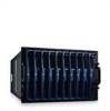
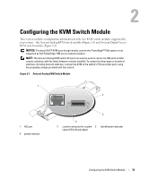
Configuring the Cisco Catalyst Blade Switch 3030 The Cisco Catalyst Blade Switch 3030 module is a 16-port switch with 10 downlinks, 6 uplinks, and one console port: • Four uplinks accommodate copper and fiber Small Form-Factor Pluggable (SFP) modules. Two uplinks are 10/100/1000BASE-T ports. The uplinks connect to the external Ethernet network and operate at 10/100/1000 Mb. • The 10 downlinks connect to the embedded Ethernet controller on the server module and operate at 1000 Mb only. • The external console port provides an connection for a management station, using the RJ45-to-DB9 cable supplied with the module. • An internal serial management port provides access to the switch module through the DRAC/MC. For detailed information on the Cisco Catalyst Blade Switch 3030, see the documentation that shipped with the module or on support.dell.com. Before configuring the switch, obtain the following information from your network administrator: • Username and password • The IP address to be assigned to the VLAN 1 interface through which the device is to be managed • The IP subnet mask for the network • The IP address of the default gateway Configuring the Cisco Switch Using a Web Browser and a Management Station When you power-up the switch for the first time, an automatic setup program runs to assign IP information and to create a default configuration for continued use. 1 Connect a management station to the console connection on the switch, or use the DRAC/MC web interface. 2 Type http://10.0.0.1 in the web browser, and press Enter. 3 When the Network Settings window appears, enter the following values: • The IP address of the switch. • The IP subnet mask for the network. • The IP address of the default gateway. • A password value in the Switch Password field. • (Optional) a name for the switch in the Host Name field. • If you will use Telnet to manage the switch, set the Telnet Access field to Enable, and enter a password value in the Telnet Password field. Do not change the Management Interface default VLAN ID value of 1 unless you intend to change the switch's management interface value. 4 Click Submit to update the switch configuration. General System Configuration 29
-
 1
1 -
2
-
3
-
4
-
5
-
6
-
7
-
8
-
9
-
10
-
11
-
12
-
13
-
14
-
15
-
16
-
17
-
18
-
19
-
20
-
21
-
22
-
23
-
24
-
25
-
 26
26 -
 27
27 -
 28
28 -
 29
29 -
 30
30 -
 31
31 -
 32
32 -
 33
33 -
 34
34 -
 35
35 -
 36
36 -
37
-
38
-
39
-
40
-
41
-
42
-
43
-
44
-
45
-
46
-
47
-
48
-
49
-
50
-
51
-
52
-
53
-
54
-
55
-
56
-
57
-
58
-
59
-
60
-
61
-
62
-
63
-
64
-
65
-
66
-
67
-
68
-
69
-
70
-
71
-
72
-
73
-
74
-
75
-
76
-
77
-
78
-
79
-
80
-
81
-
82
-
83
-
84
-
85
-
86
-
87
-
88
-
89
-
90
-
91
-
92
-
93
-
94
-
95
-
96
-
97
-
98
-
99
-
100
-
101
-
102
-
103
-
104
-
105
-
106
-
107
-
108
-
109
-
110
-
111
-
112
-
113
-
114
-
115
-
116
-
117
-
118
-
119
-
120
-
121
-
122
-
123
-
124
-
125
-
126
-
127
-
128
-
129
-
130
-
131
-
132
-
133
-
134
-
135
-
136
-
137
-
138
-
139
-
140
-
141
-
142
-
143
-
144
-
145
-
146
-
147
-
148
-
149
-
150
-
151
-
152
-
153
-
154
-
155
-
156
-
157
-
158
-
159
-
160
-
161
-
162
-
163
-
164
-
165
-
166
-
167
-
168
-
169
-
170
-
171
-
172
-
173
-
174
-
175
-
176
-
177
-
178
-
179
-
180
-
181
-
182
-
183
-
184
-
185
-
186
-
187
-
188
-
189
-
190
-
191
-
192
-
193
-
194
-
195
-
196
-
197
-
198
-
199
-
200
-
201
-
202
-
203
-
204
-
205
-
206
 |
 |