Dell PowerEdge C6520 EMC Installation and Service Manual - Page 10
Sled to hard drive mapping
 |
View all Dell PowerEdge C6520 manuals
Add to My Manuals
Save this manual to your list of manuals |
Page 10 highlights
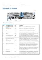
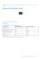
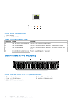
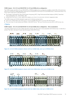
Figure 4. Ethernet port indicator codes 1. Speed indicator 2. Link and activity indicator Table 3. Ethernet port indicator codes Convention Status Condition A Link and activity indicators are off The NIC is not connected to the network. B Link indicator is green The NIC is connected to a valid network at its maximum port speed. C Link indicator is amber The NIC is connected to a valid network at less than its maximum port speed. D Activity indicator is flashing green Network data is being sent or received. Sled to hard drive mapping Figure 5. Sled to drive mapping for 24 x 2.5-inch drive configuration 1. Drives 0-5 mapped to sled 1 3. Drives 12-17 mapped to sled 3 5. (Optional) NVMe hard drive location 2. Drives 6-11 mapped to sled 2 4. Drives 18-23 mapped to sled 4 10 Dell EMC PowerEdge C6520 system overview
-
 1
1 -
2
-
3
-
4
-
 5
5 -
 6
6 -
 7
7 -
 8
8 -
 9
9 -
 10
10 -
 11
11 -
 12
12 -
 13
13 -
 14
14 -
 15
15 -
16
-
17
-
18
-
19
-
20
-
21
-
22
-
23
-
24
-
25
-
26
-
27
-
28
-
29
-
30
-
31
-
32
-
33
-
34
-
35
-
36
-
37
-
38
-
39
-
40
-
41
-
42
-
43
-
44
-
45
-
46
-
47
-
48
-
49
-
50
-
51
-
52
-
53
-
54
-
55
-
56
-
57
-
58
-
59
-
60
-
61
-
62
-
63
-
64
-
65
-
66
-
67
-
68
-
69
-
70
-
71
-
72
-
73
-
74
-
75
-
76
-
77
-
78
-
79
-
80
-
81
-
82
-
83
-
84
-
85
-
86
-
87
-
88
-
89
 |
 |
