Dell PowerEdge C6520 EMC Installation and Service Manual - Page 68
Installing the processor and heat sink PHM
 |
View all Dell PowerEdge C6520 manuals
Add to My Manuals
Save this manual to your list of manuals |
Page 68 highlights
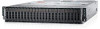
Figure 75. Installing the processor and heat sink (PHM) 3. Set the Anti-Tilt wires to the locked position (outward position), and then using the Torx #T30 screwdriver, tighten the screws (8 in-lbf) on the heat sink in the order below: a. Tighten the first screw three turns. b. Tighten the screw diagonally opposite to the screw you tighten first. c. Repeat the procedure for the remaining two screws. d. Return to the first screw to tighten it completely. 68 Installing and removing system components
-
 1
1 -
2
-
3
-
4
-
5
-
6
-
7
-
8
-
9
-
10
-
11
-
12
-
13
-
14
-
15
-
16
-
17
-
18
-
19
-
20
-
21
-
22
-
23
-
24
-
25
-
26
-
27
-
28
-
29
-
30
-
31
-
32
-
33
-
34
-
35
-
36
-
37
-
38
-
39
-
40
-
41
-
42
-
43
-
44
-
45
-
46
-
47
-
48
-
49
-
50
-
51
-
52
-
53
-
54
-
55
-
56
-
57
-
58
-
59
-
60
-
61
-
62
-
 63
63 -
 64
64 -
 65
65 -
 66
66 -
 67
67 -
 68
68 -
 69
69 -
 70
70 -
 71
71 -
 72
72 -
 73
73 -
74
-
75
-
76
-
77
-
78
-
79
-
80
-
81
-
82
-
83
-
84
-
85
-
86
-
87
-
88
-
89
 |
 |

Figure 75. Installing the processor and heat sink (PHM)
3.
Set the Anti-Tilt wires to the locked position (outward position), and then using the Torx #T30 screwdriver, tighten the
screws (8 in-lbf) on the heat sink in the order below:
a.
Tighten the first screw three turns.
b.
Tighten the screw diagonally opposite to the screw you tighten first.
c.
Repeat the procedure for the remaining two screws.
d.
Return to the first screw to tighten it completely.
68
Installing and removing system components