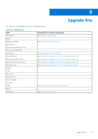
Dell PowerEdge C6520 EMC Installation and Service Manual - Page 77
Installing the system board
 |
View all Dell PowerEdge C6520 manuals
Add to My Manuals
Save this manual to your list of manuals |
Page 77 highlights
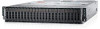
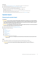
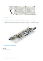
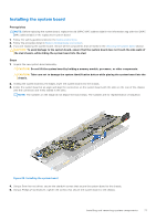
Installing the system board Prerequisites NOTE: Before replacing the system board, replace the old iDRAC MAC address label in the Information tag with the iDRAC MAC address label of the replacement system board 1. Follow the safety guidelines listed in the Safety instructions. 2. Follow the procedure listed in Before working inside your system. 3. If you are replacing the system board, remove all the components that are listed in the removing the system board section. CAUTION: To avoid damage to the system board, ensure that the system board does not touch the side walls of the sled chassis, while sliding the system board into the sled. Steps 1. Unpack the new system board assembly. CAUTION: Do not lift the system board by holding a memory module, processor, or other components. CAUTION: Take care not to damage the system identification button while placing the system board into the chassis. 2. Holding the system board by the edges, lower the system board into the chassis. 3. Incline the system board at an angle and align the connectors on the system board with the slots on the rear of the chassis until the connectors are firmly seated in the slots. NOTE: The numbers on the image do not depict the exact steps. The numbers are for representation of sequence. Figure 85. Installing the system board 4. Using a 5mm hex nut driver, secure the standoff screws that secure the system board to the chassis. 5. Using a Phillips #1 screwdriver, tighten the screws that secure the system board to the chassis. Installing and removing system components 77
-
 1
1 -
2
-
3
-
4
-
5
-
6
-
7
-
8
-
9
-
10
-
11
-
12
-
13
-
14
-
15
-
16
-
17
-
18
-
19
-
20
-
21
-
22
-
23
-
24
-
25
-
26
-
27
-
28
-
29
-
30
-
31
-
32
-
33
-
34
-
35
-
36
-
37
-
38
-
39
-
40
-
41
-
42
-
43
-
44
-
45
-
46
-
47
-
48
-
49
-
50
-
51
-
52
-
53
-
54
-
55
-
56
-
57
-
58
-
59
-
60
-
61
-
62
-
63
-
64
-
65
-
66
-
67
-
68
-
69
-
70
-
71
-
 72
72 -
 73
73 -
 74
74 -
 75
75 -
 76
76 -
 77
77 -
 78
78 -
 79
79 -
 80
80 -
 81
81 -
 82
82 -
83
-
84
-
85
-
86
-
87
-
88
-
89
 |
 |
