Dell PowerEdge C6520 EMC Installation and Service Manual - Page 36
Removing the expansion card riser 1, Table 11. Configuration 3: R1b continued
 |
View all Dell PowerEdge C6520 manuals
Add to My Manuals
Save this manual to your list of manuals |
Page 36 highlights
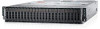
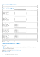
Table 11. Configuration 3: R1b (continued) Card type Slot priority Dell BOSS M.2 Module Integrated slot Table 12. Configuration 4: R1b+R2b Card type Slot priority Broadcom (NIC: 25G) 2 Broadcom (NIC: 10G) 2 Intel (NIC: 10G) 2 Broadcom (NIC: 25G) 2 Intel (NIC: 1G) 2 Mellanox (NIC: 100Gb) 1 Intel (NIC: 25Gb) 2 Mellanox (NIC: 25Gb) 2 SolarFlare (NIC: 25Gb) 2 Mellanox (NIC: HDR100 VPI) 2 Mellanox (NIC: HDR VPI) 2 Intel (OCP: 100Gb) Integrated slot Broadcom (OCP: 25Gb) Integrated slot Intel (OCP: 25Gb) Integrated slot Marvell (OCP: 25Gb) Integrated slot Mellanox (OCP: 25Gb) Integrated slot QLogic (OCP: 25Gb) Integrated slot Broadcom (OCP: 10Gb) Integrated slot QLogic (OCP: 10Gb) Integrated slot Intel (OCP: 10Gb) Integrated slot Broadcom (OCP: 1Gb) Integrated slot Intel (OCP: 1Gb) Integrated slot Dell BOSS M.2 Module Integrated slot Intel (PCIe SSD AIC) 2 Samsung (PCIe SSD AIC) 2 Nvidia (GPU: T4 16 GB) 2 Maximum number of cards 1 Maximum number of cards 2 2 2 2 2 2 2 2 2 2 2 1 1 1 1 1 1 1 1 1 1 1 1 1 1 1 Removing the expansion card riser 1 Prerequisites NOTE: Install an expansion card filler bracket over an empty expansion slot to maintain Federal Communications Commission (FCC) certification of the system. The brackets also keep dust and dirt out of the system and aid in proper cooling and airflow inside the system. 1. Follow the safety guidelines listed in Safety instructions. 2. Follow the procedure listed in Before working inside your system. 3. Remove the air shroud. 36 Installing and removing system components
-
 1
1 -
2
-
3
-
4
-
5
-
6
-
7
-
8
-
9
-
10
-
11
-
12
-
13
-
14
-
15
-
16
-
17
-
18
-
19
-
20
-
21
-
22
-
23
-
24
-
25
-
26
-
27
-
28
-
29
-
30
-
 31
31 -
 32
32 -
 33
33 -
 34
34 -
 35
35 -
 36
36 -
 37
37 -
 38
38 -
 39
39 -
 40
40 -
 41
41 -
42
-
43
-
44
-
45
-
46
-
47
-
48
-
49
-
50
-
51
-
52
-
53
-
54
-
55
-
56
-
57
-
58
-
59
-
60
-
61
-
62
-
63
-
64
-
65
-
66
-
67
-
68
-
69
-
70
-
71
-
72
-
73
-
74
-
75
-
76
-
77
-
78
-
79
-
80
-
81
-
82
-
83
-
84
-
85
-
86
-
87
-
88
-
89
 |
 |
