Dell PowerEdge C6520 EMC Installation and Service Manual - Page 75
System board, Removing the system board
 |
View all Dell PowerEdge C6520 manuals
Add to My Manuals
Save this manual to your list of manuals |
Page 75 highlights
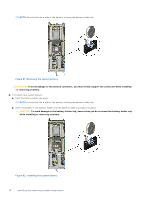
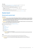
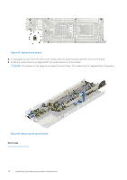
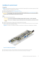
Next steps 1. If applicable, Install the expansion card riser 1 and connect the cables to the expansion card. 2. Follow the procedure listed in the After working inside your system. 3. Confirm that the battery is operating properly, by performing the following steps: a. Enter the System Setup, while booting, by pressing F2. b. Enter the correct time and date in the System Setup Time and Date fields. c. Exit the System Setup. d. To test the newly installed battery, remove the system from the enclosure for at least an hour. e. Reinstall the system into the enclosure after an hour. f. Enter the System Setup and if the time and date are still incorrect, see Getting help section. System board Removing the system board Prerequisites CAUTION: If you are using the Trusted Platform Module (TPM) with an encryption key, you may be prompted to create a recovery key during program or System Setup. Be sure to create and safely store this recovery key. If you replace this system board, you must supply the recovery key when you restart your system or program before you can access the encrypted data on your drives. CAUTION: To avoid damage to the system board, ensure that the system board does not touch the side walls of the sled chassis, while sliding the system board into the sled. 1. Follow the safety guidelines listed in the Safety instructions. 2. Follow the procedure listed in Before working inside your system. 3. Remove the following components: a. Sled b. Air shroud c. Expansion card risers d. Heat sink module e. Processor f. Memory modules g. If installed, OCP card h. Linking board i. Disconnect all cables from the system board. CAUTION: Take care not to damage the system identification button while removing the system board from the sled. Steps 1. Using a Phillips #1 screwdriver, remove the screws that secure the system board to the chassis. 2. Using a 5mm hex nut driver, remove the standoff screws that secure the system board to the chassis. CAUTION: Do not lift the system board by holding a memory module slot, any other connector, or component. Installing and removing system components 75
-
 1
1 -
2
-
3
-
4
-
5
-
6
-
7
-
8
-
9
-
10
-
11
-
12
-
13
-
14
-
15
-
16
-
17
-
18
-
19
-
20
-
21
-
22
-
23
-
24
-
25
-
26
-
27
-
28
-
29
-
30
-
31
-
32
-
33
-
34
-
35
-
36
-
37
-
38
-
39
-
40
-
41
-
42
-
43
-
44
-
45
-
46
-
47
-
48
-
49
-
50
-
51
-
52
-
53
-
54
-
55
-
56
-
57
-
58
-
59
-
60
-
61
-
62
-
63
-
64
-
65
-
66
-
67
-
68
-
69
-
 70
70 -
 71
71 -
 72
72 -
 73
73 -
 74
74 -
 75
75 -
 76
76 -
 77
77 -
 78
78 -
 79
79 -
 80
80 -
81
-
82
-
83
-
84
-
85
-
86
-
87
-
88
-
89
 |
 |
