Dell PowerEdge C6520 EMC Installation and Service Manual - Page 24
After working inside your system, Recommended tools, Sled, Sled installation guidelines
 |
View all Dell PowerEdge C6520 manuals
Add to My Manuals
Save this manual to your list of manuals |
Page 24 highlights
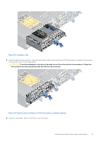
After working inside your system Prerequisites Follow the safety guidelines listed in Safety instructions. Steps 1. If applicable, remove the I/O connector cover from the system connectors. Install the sled into the enclosure. 2. Reconnect the peripherals and connect the system to the electrical outlet, and then power on the system. Recommended tools You need the following tools to perform the removal and installation procedures: ● Phillips #1 screwdriver ● Phillips #2 screwdriver ● Torx #T30 screwdriver ● 5 mm hex nut screwdriver ● Plastic scribe ● 1/4-inch flat blade screwdriver ● Wrist grounding strap connected to the ground ● ESD mat Sled Sled installation guidelines CAUTION: Ensure that the chassis does not have a mixed architecture of PowerEdge C6420, PowerEdge C6525 and PowerEdge C6520 sled configurations. NOTE: Ensure to install a sled blank in all the empty slots. Operating the enclosure without a blank results in overheating. NOTE: For optimized thermal operation, do not mix single processor and dual processor sleds within the same chassis. NOTE: For optimized thermal operation, ensure to follow the sled population sequence shown in the image below: 24 Installing and removing system components
-
 1
1 -
2
-
3
-
4
-
5
-
6
-
7
-
8
-
9
-
10
-
11
-
12
-
13
-
14
-
15
-
16
-
17
-
18
-
 19
19 -
 20
20 -
 21
21 -
 22
22 -
 23
23 -
 24
24 -
 25
25 -
 26
26 -
 27
27 -
 28
28 -
 29
29 -
30
-
31
-
32
-
33
-
34
-
35
-
36
-
37
-
38
-
39
-
40
-
41
-
42
-
43
-
44
-
45
-
46
-
47
-
48
-
49
-
50
-
51
-
52
-
53
-
54
-
55
-
56
-
57
-
58
-
59
-
60
-
61
-
62
-
63
-
64
-
65
-
66
-
67
-
68
-
69
-
70
-
71
-
72
-
73
-
74
-
75
-
76
-
77
-
78
-
79
-
80
-
81
-
82
-
83
-
84
-
85
-
86
-
87
-
88
-
89
 |
 |
