Dell PowerEdge T140 EMC Installation and Service Manual - Page 9
Front view of the system
 |
View all Dell PowerEdge T140 manuals
Add to My Manuals
Save this manual to your list of manuals |
Page 9 highlights
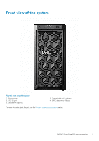
Front view of the system Figure 1. Front view of the system 1. Power button 3. USB 3.0 port 5. Optical drive (optional) 2. System health and ID indicator 4. iDRAC direct micro USB port For more information about the ports, see the Ports and connectors specifications section. Dell EMC PowerEdge T140 system overview 9
-
 1
1 -
2
-
3
-
 4
4 -
 5
5 -
 6
6 -
 7
7 -
 8
8 -
 9
9 -
 10
10 -
 11
11 -
 12
12 -
 13
13 -
 14
14 -
15
-
16
-
17
-
18
-
19
-
20
-
21
-
22
-
23
-
24
-
25
-
26
-
27
-
28
-
29
-
30
-
31
-
32
-
33
-
34
-
35
-
36
-
37
-
38
-
39
-
40
-
41
-
42
-
43
-
44
-
45
-
46
-
47
-
48
-
49
-
50
-
51
-
52
-
53
-
54
-
55
-
56
-
57
-
58
-
59
-
60
-
61
-
62
-
63
-
64
-
65
-
66
-
67
-
68
-
69
-
70
-
71
-
72
-
73
-
74
-
75
-
76
-
77
-
78
-
79
-
80
-
81
-
82
-
83
-
84
-
85
-
86
-
87
-
88
-
89
-
90
-
91
-
92
-
93
-
94
-
95
-
96
-
97
-
98
-
99
-
100
-
101
-
102
 |
 |
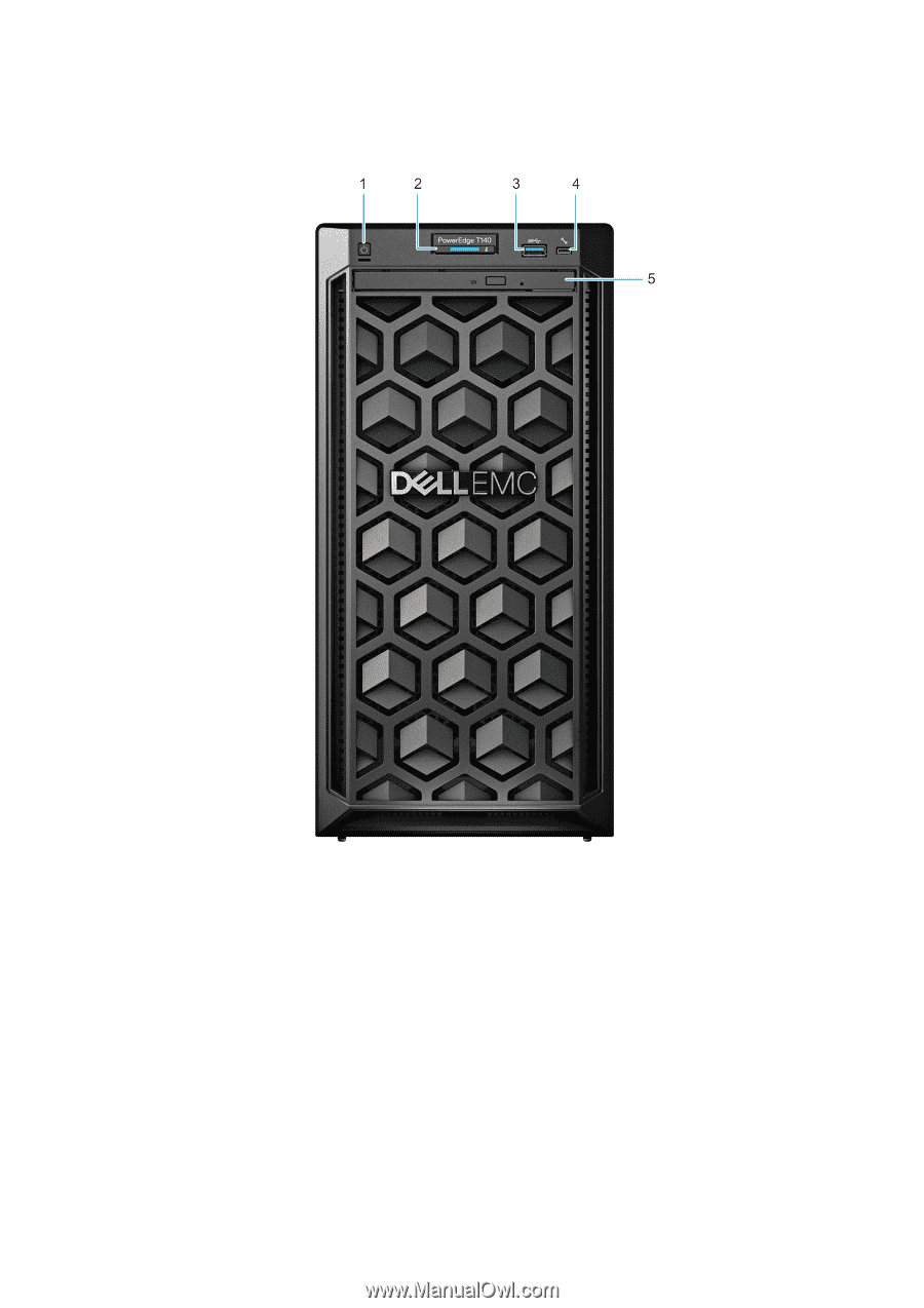
Front view of the system
Figure 1. Front view of the system
1.
Power button
2.
System health and ID indicator
3.
USB 3.0 port
4.
iDRAC direct micro USB port
5.
Optical drive (optional)
For more information about the ports, see the
Ports and connectors specifications
section.
Dell EMC PowerEdge T140 system overview
9