Dell XPS 720 Black Owner's Manual - Page 128
Processor Airflow Shroud, Removing the Processor Airflow Shroud Assembly
 |
View all Dell XPS 720 Black manuals
Add to My Manuals
Save this manual to your list of manuals |
Page 128 highlights
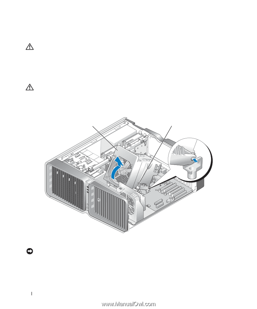
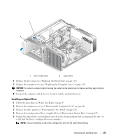
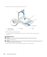
Processor Airflow Shroud CAUTION: Before you perform this procedure, follow the safety instructions located in the Product Information Guide. Removing the Processor Airflow Shroud Assembly 1 Follow the procedures in "Before You Begin" on page 85. 2 Remove the computer cover (see "Removing the Computer Cover" on page 86). CAUTION: The processor heat sink can get very hot during normal operation. Be sure that the heat sink has had sufficient time to cool before you touch it. 3 Disconnect the fan cable from the FAN1_CPU connector on the system board (see "System Board Components" on page 89). 1 2 1 processor airflow shroud 2 captive screws (2) NOTICE: The processor heat sink is attached to the processor airflow shroud. When you remove the airflow shroud, lay it upside down or on its side to avoid damaging the heatsink thermal interface. 4 Loosen the captive screws securing the processor airflow shroud to the chassis, then rotate the shroud back. 5 Lift the processor airflow shroud out of the computer, and then set it aside. 128 Removing and Installing Parts
-
 1
1 -
2
-
3
-
4
-
5
-
6
-
7
-
8
-
9
-
10
-
11
-
12
-
13
-
14
-
15
-
16
-
17
-
18
-
19
-
20
-
21
-
22
-
23
-
24
-
25
-
26
-
27
-
28
-
29
-
30
-
31
-
32
-
33
-
34
-
35
-
36
-
37
-
38
-
39
-
40
-
41
-
42
-
43
-
44
-
45
-
46
-
47
-
48
-
49
-
50
-
51
-
52
-
53
-
54
-
55
-
56
-
57
-
58
-
59
-
60
-
61
-
62
-
63
-
64
-
65
-
66
-
67
-
68
-
69
-
70
-
71
-
72
-
73
-
74
-
75
-
76
-
77
-
78
-
79
-
80
-
81
-
82
-
83
-
84
-
85
-
86
-
87
-
88
-
89
-
90
-
91
-
92
-
93
-
94
-
95
-
96
-
97
-
98
-
99
-
100
-
101
-
102
-
103
-
104
-
105
-
106
-
107
-
108
-
109
-
110
-
111
-
112
-
113
-
114
-
115
-
116
-
117
-
118
-
119
-
120
-
121
-
122
-
 123
123 -
 124
124 -
 125
125 -
 126
126 -
 127
127 -
 128
128 -
 129
129 -
 130
130 -
 131
131 -
 132
132 -
 133
133 -
134
-
135
-
136
-
137
-
138
-
139
-
140
-
141
-
142
-
143
-
144
-
145
-
146
-
147
-
148
-
149
-
150
-
151
-
152
-
153
-
154
-
155
-
156
-
157
-
158
-
159
-
160
-
161
-
162
-
163
-
164
-
165
-
166
-
167
-
168
-
169
-
170
-
171
-
172
-
173
-
174
-
175
-
176
-
177
-
178
-
179
-
180
-
181
-
182
-
183
-
184
-
185
-
186
-
187
-
188
-
189
-
190
-
191
-
192
-
193
-
194
-
195
-
196
-
197
-
198
-
199
-
200
-
201
-
202
-
203
-
204
-
205
-
206
-
207
-
208
-
209
-
210
-
211
-
212
-
213
-
214
-
215
-
216
-
217
-
218
 |
 |