Dell XPS 720 Black Owner's Manual - Page 157
Installing the I/O Panel, Battery, Replacing the Battery
 |
View all Dell XPS 720 Black manuals
Add to My Manuals
Save this manual to your list of manuals |
Page 157 highlights
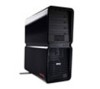
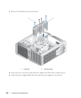
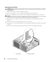
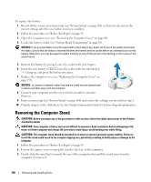
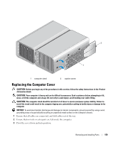
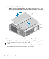
8 Remove the four mounting screws from the I/O panel. 9 Lift to remove the I/O panel from the computer. Installing the I/O Panel CAUTION: Before you begin any of the procedures in this section, follow the safety instructions in the Product Information Guide. NOTICE: Ensure that you replace all cables originally attached to the I/O panel or you computer may not function properly. 1 Follow the procedures in "Before You Begin" on page 85. 2 Remove the computer cover (see "Removing the Computer Cover" on page 86). 3 Align the screw holes on the I/O panel with the screw holes on the chassis, and then tighten the four mounting screws. 4 Connect the control-panel cable to the I/O panel connector. 5 Replace the processor and card fan assembly. 6 Connect the front fan and the card fan to the system board. 7 Replace the processor airflow shroud (see "Installing the Processor Airflow Shroud Assembly" on page 129). 8 Replace any full-length expansion cards (see "Installing PCI and PCI Express Cards" on page 97) that were uninstalled during removal of the I/O panel. 9 Replace the computer cover (see "Replacing the Computer Cover" on page 159). Battery CAUTION: Before you begin any of the procedures in this section, follow the safety instructions in the Product Information Guide. Replacing the Battery A coin-cell battery maintains computer configuration, date, and time information. The battery can last several years. If you have to repeatedly reset time and date information after turning on the computer, replace the battery. CAUTION: A new battery can explode if it is incorrectly installed. Replace the battery only with the same or equivalent type recommended by the manufacturer. Discard used batteries according to the manufacturer's instructions. Removing and Installing Parts 157
-
 1
1 -
2
-
3
-
4
-
5
-
6
-
7
-
8
-
9
-
10
-
11
-
12
-
13
-
14
-
15
-
16
-
17
-
18
-
19
-
20
-
21
-
22
-
23
-
24
-
25
-
26
-
27
-
28
-
29
-
30
-
31
-
32
-
33
-
34
-
35
-
36
-
37
-
38
-
39
-
40
-
41
-
42
-
43
-
44
-
45
-
46
-
47
-
48
-
49
-
50
-
51
-
52
-
53
-
54
-
55
-
56
-
57
-
58
-
59
-
60
-
61
-
62
-
63
-
64
-
65
-
66
-
67
-
68
-
69
-
70
-
71
-
72
-
73
-
74
-
75
-
76
-
77
-
78
-
79
-
80
-
81
-
82
-
83
-
84
-
85
-
86
-
87
-
88
-
89
-
90
-
91
-
92
-
93
-
94
-
95
-
96
-
97
-
98
-
99
-
100
-
101
-
102
-
103
-
104
-
105
-
106
-
107
-
108
-
109
-
110
-
111
-
112
-
113
-
114
-
115
-
116
-
117
-
118
-
119
-
120
-
121
-
122
-
123
-
124
-
125
-
126
-
127
-
128
-
129
-
130
-
131
-
132
-
133
-
134
-
135
-
136
-
137
-
138
-
139
-
140
-
141
-
142
-
143
-
144
-
145
-
146
-
147
-
148
-
149
-
150
-
151
-
 152
152 -
 153
153 -
 154
154 -
 155
155 -
 156
156 -
 157
157 -
 158
158 -
 159
159 -
 160
160 -
 161
161 -
 162
162 -
163
-
164
-
165
-
166
-
167
-
168
-
169
-
170
-
171
-
172
-
173
-
174
-
175
-
176
-
177
-
178
-
179
-
180
-
181
-
182
-
183
-
184
-
185
-
186
-
187
-
188
-
189
-
190
-
191
-
192
-
193
-
194
-
195
-
196
-
197
-
198
-
199
-
200
-
201
-
202
-
203
-
204
-
205
-
206
-
207
-
208
-
209
-
210
-
211
-
212
-
213
-
214
-
215
-
216
-
217
-
218
 |
 |