Dell XPS 720 Black Owner's Manual - Page 90
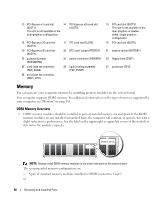
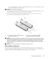
Memory, DDR2 Memory Overview
 |
View all Dell XPS 720 Black manuals
Add to My Manuals
Save this manual to your list of manuals |
Page 90 highlights
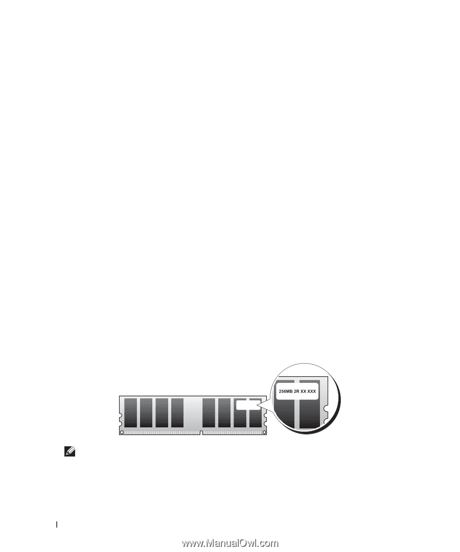
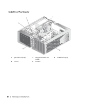
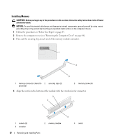
13 PCI-Express x1 card slot 14 PCI-Express x16 card slot (SLOT1) (SLOT2) This slot is not available in the dual-graphics configuration 16 PCI-Express x16 card slot (SLOT4) 19 PCI-Express x16 card slot (SLOT7) 22 password jumper (PASSWORD) 25 card cage fan connector (FAN_CAGE) 28 processor fan connector (FAN1_CPU) 17 PCI card slot (SLOT5) 20 RTC reset jumper (RTCRST) 23 power connector (POWER2) 26 liquid cooling assembly (TEC_PUMP) 15 PCI card slot (SLOT3) This slot is not available in the dual-graphics or doublewidth, single graphics configuration. 18 PCI card slot (SLOT6) 21 battery socket (BATTERY) 24 floppy drive (DSKT) 27 processor (CPU) Memory You can increase your computer memory by installing memory modules on the system board. Your computer supports DDR2 memory. For additional information on the type of memory supported by your computer, see "Memory" on page 161. DDR2 Memory Overview • DDR2 memory modules should be installed in pairs of matched memory size and speed. If the DDR2 memory modules are not installed in matched pairs, the computer will continue to operate, but with a slight reduction in performance. See the label on the upper-right or upper-left corner of the module to determine the module's capacity. NOTE: Always install DDR2 memory modules in the order indicated on the system board. The recommended memory configurations are: - A pair of matched memory modules installed in DIMM connectors 1 and 2 or 90 Removing and Installing Parts
-
 1
1 -
2
-
3
-
4
-
5
-
6
-
7
-
8
-
9
-
10
-
11
-
12
-
13
-
14
-
15
-
16
-
17
-
18
-
19
-
20
-
21
-
22
-
23
-
24
-
25
-
26
-
27
-
28
-
29
-
30
-
31
-
32
-
33
-
34
-
35
-
36
-
37
-
38
-
39
-
40
-
41
-
42
-
43
-
44
-
45
-
46
-
47
-
48
-
49
-
50
-
51
-
52
-
53
-
54
-
55
-
56
-
57
-
58
-
59
-
60
-
61
-
62
-
63
-
64
-
65
-
66
-
67
-
68
-
69
-
70
-
71
-
72
-
73
-
74
-
75
-
76
-
77
-
78
-
79
-
80
-
81
-
82
-
83
-
84
-
 85
85 -
 86
86 -
 87
87 -
 88
88 -
 89
89 -
 90
90 -
 91
91 -
 92
92 -
 93
93 -
 94
94 -
 95
95 -
96
-
97
-
98
-
99
-
100
-
101
-
102
-
103
-
104
-
105
-
106
-
107
-
108
-
109
-
110
-
111
-
112
-
113
-
114
-
115
-
116
-
117
-
118
-
119
-
120
-
121
-
122
-
123
-
124
-
125
-
126
-
127
-
128
-
129
-
130
-
131
-
132
-
133
-
134
-
135
-
136
-
137
-
138
-
139
-
140
-
141
-
142
-
143
-
144
-
145
-
146
-
147
-
148
-
149
-
150
-
151
-
152
-
153
-
154
-
155
-
156
-
157
-
158
-
159
-
160
-
161
-
162
-
163
-
164
-
165
-
166
-
167
-
168
-
169
-
170
-
171
-
172
-
173
-
174
-
175
-
176
-
177
-
178
-
179
-
180
-
181
-
182
-
183
-
184
-
185
-
186
-
187
-
188
-
189
-
190
-
191
-
192
-
193
-
194
-
195
-
196
-
197
-
198
-
199
-
200
-
201
-
202
-
203
-
204
-
205
-
206
-
207
-
208
-
209
-
210
-
211
-
212
-
213
-
214
-
215
-
216
-
217
-
218
 |
 |