Epson ActionTower 3000 User Manual - Page 87
casing or printed on the drive's circuit board to identify
 |
View all Epson ActionTower 3000 manuals
Add to My Manuals
Save this manual to your list of manuals |
Page 87 highlights
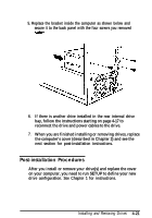
6. Place the bracket into the computer as shown below and secure it to the back panel with the four screws you removed from the back of the computer. 7. To connect the drive ribbon cables to the drives in the rear internal bay, first locate pin 1 on each drive's connector. The number "1" or "2" may be stamped on the connector casing or printed on the drive's circuit board to identify the side of the connector containing pin 1. If the number does not appear on the connector casing, remove the drive and turn it over to check the circuit board. Installing and Removing Drives 4-17
-
 1
1 -
2
-
3
-
4
-
5
-
6
-
7
-
8
-
9
-
10
-
11
-
12
-
13
-
14
-
15
-
16
-
17
-
18
-
19
-
20
-
21
-
22
-
23
-
24
-
25
-
26
-
27
-
28
-
29
-
30
-
31
-
32
-
33
-
34
-
35
-
36
-
37
-
38
-
39
-
40
-
41
-
42
-
43
-
44
-
45
-
46
-
47
-
48
-
49
-
50
-
51
-
52
-
53
-
54
-
55
-
56
-
57
-
58
-
59
-
60
-
61
-
62
-
63
-
64
-
65
-
66
-
67
-
68
-
69
-
70
-
71
-
72
-
73
-
74
-
75
-
76
-
77
-
78
-
79
-
80
-
81
-
 82
82 -
 83
83 -
 84
84 -
 85
85 -
 86
86 -
 87
87 -
 88
88 -
 89
89 -
 90
90 -
 91
91 -
 92
92 -
93
-
94
-
95
-
96
-
97
-
98
-
99
-
100
-
101
-
102
-
103
-
104
-
105
-
106
-
107
-
108
-
109
-
110
-
111
-
112
-
113
-
114
-
115
-
116
-
117
-
118
-
119
-
120
-
121
-
122
-
123
-
124
-
125
-
126
-
127
-
128
-
129
-
130
-
131
-
132
-
133
-
134
-
135
-
136
-
137
 |
 |

6.
Place the bracket into the computer as shown below and
secure it to the back panel with the four screws you
removed from the back of the computer.
7.
To connect the drive ribbon cables to the drives in the rear
internal bay, first locate pin 1 on each drive’s connector.
The number “1” or “2” may be stamped on the connector
casing or printed on the drive’s circuit board to identify the
side of the connector containing pin 1. If the number does
not appear on the connector casing, remove the drive and
turn it over to check the circuit board.
Installing and Removing Drives
4-17