Epson FX 1170 Service Manual - Page 105
Overview, at 25 degrees - problem
 |
View all Epson FX 1170 manuals
Add to My Manuals
Save this manual to your list of manuals |
Page 105 highlights
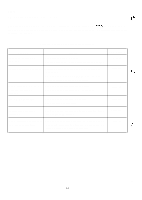
5.1 Overview REV.-A The FX-870/l 170 may exhibit different symptoms for the same problem. This makes troubleshooting difficult. This section provides simple and effective ways to facilitate troubleshooting. The following flowchart illustrates the main steps of the troubleshooting process. TSTART r 1 I 5.3 I 5-1o I 5.4 15-10 I 5.5 5-13 ~ The problem is corrected. ] Figure 5-1. The Troubleshooting Procedure The following tables provide troubleshooting information. Part Motor Assembly, CR I Motor Assembly, PF Printhead Table 5-1. Motor and Printhead Coil Resistance Coil Resistance 5.0 ohms +/- 77. at 25 degrees C (77degrees F) CN13 on the main board 1,2,3, 4 pin@ phase A, ~, B, ~ 63 ohms +/-3 ohms at 25 degrees C (77degrees F) CN6 on the main board 1,2,3, 4 pin~ phase A, ~, B, ~ 16.5 ohms +/- 1.6 ohms at 25 degrees C (77degrees F) (Refer to Figure 5-2. of the head wire arrengement.) 5-1
-
 1
1 -
2
-
3
-
4
-
5
-
6
-
7
-
8
-
9
-
10
-
11
-
12
-
13
-
14
-
15
-
16
-
17
-
18
-
19
-
20
-
21
-
22
-
23
-
24
-
25
-
26
-
27
-
28
-
29
-
30
-
31
-
32
-
33
-
34
-
35
-
36
-
37
-
38
-
39
-
40
-
41
-
42
-
43
-
44
-
45
-
46
-
47
-
48
-
49
-
50
-
51
-
52
-
53
-
54
-
55
-
56
-
57
-
58
-
59
-
60
-
61
-
62
-
63
-
64
-
65
-
66
-
67
-
68
-
69
-
70
-
71
-
72
-
73
-
74
-
75
-
76
-
77
-
78
-
79
-
80
-
81
-
82
-
83
-
84
-
85
-
86
-
87
-
88
-
89
-
90
-
91
-
92
-
93
-
94
-
95
-
96
-
97
-
98
-
99
-
 100
100 -
 101
101 -
 102
102 -
 103
103 -
 104
104 -
 105
105 -
 106
106 -
 107
107 -
 108
108 -
 109
109 -
 110
110 -
111
-
112
-
113
-
114
-
115
-
116
-
117
-
118
-
119
-
120
-
121
-
122
-
123
-
124
-
125
-
126
-
127
-
128
-
129
-
130
-
131
-
132
-
133
-
134
-
135
-
136
-
137
-
138
 |
 |
