Epson FX 1170 Service Manual - Page 117
Table, Repairing the BOARD ASSEMBLY, C076, Continued, Problem
 |
View all Epson FX 1170 manuals
Add to My Manuals
Save this manual to your list of manuals |
Page 117 highlights
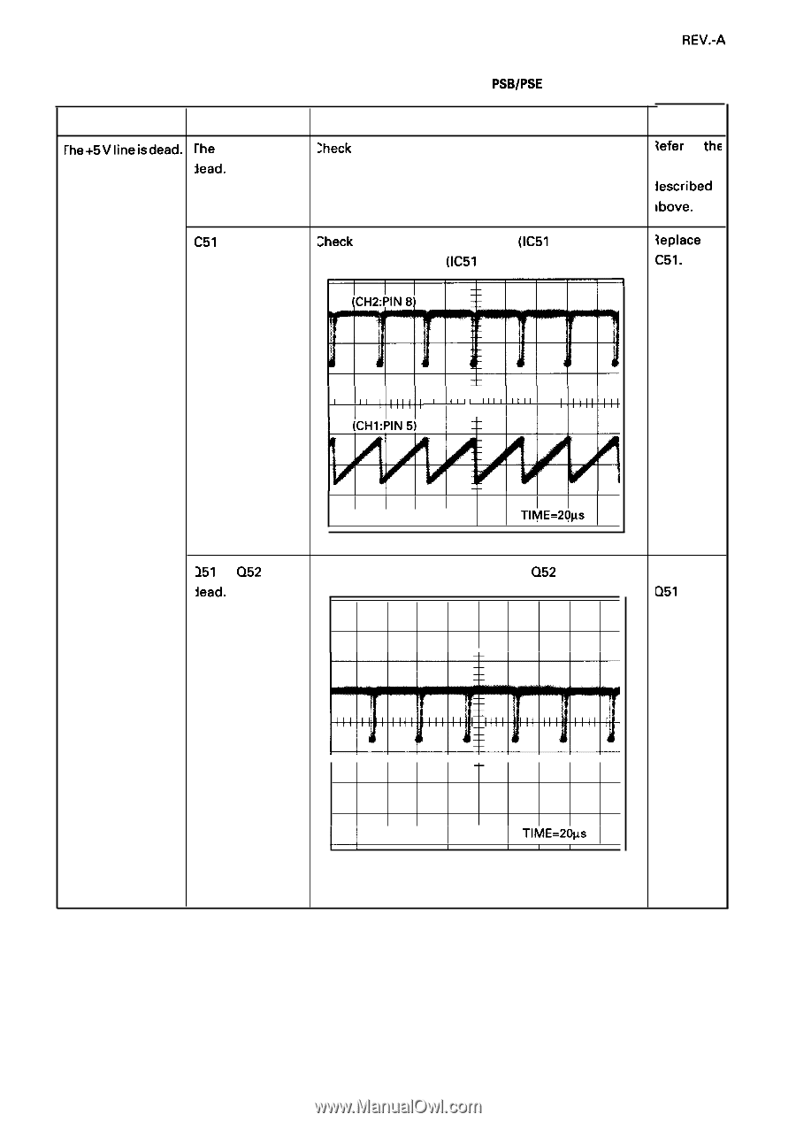
REV.-A Table 5-4. Repairing the BOARD ASSEMBLY, C076 PSB/PSE (Continued) Problem rhe+5Vlineisdead. Cause rhe +35 V line is ~ead. Checkpoint ;heck the +35 V line. Solution {efer to tht terns iescribed ]bove. C51 is dead. :heck the oscillation waveform (IC51 pin 5) and the {eplace switching waveform (IC51 pin 8 ) . C51. III III I I I + I II Ill I II II I I I 1 1 1 I CH1=2V CH2=20V 1 I TlME=20ps 251 or Q52 is iead. Check the switching waveform at Q52 emitter. -F Replace D51 or D52. 11111+1111 L II CH1=20V * 1 1 1 TlME=20~s I [ I 1 5-13
-
 1
1 -
2
-
3
-
4
-
5
-
6
-
7
-
8
-
9
-
10
-
11
-
12
-
13
-
14
-
15
-
16
-
17
-
18
-
19
-
20
-
21
-
22
-
23
-
24
-
25
-
26
-
27
-
28
-
29
-
30
-
31
-
32
-
33
-
34
-
35
-
36
-
37
-
38
-
39
-
40
-
41
-
42
-
43
-
44
-
45
-
46
-
47
-
48
-
49
-
50
-
51
-
52
-
53
-
54
-
55
-
56
-
57
-
58
-
59
-
60
-
61
-
62
-
63
-
64
-
65
-
66
-
67
-
68
-
69
-
70
-
71
-
72
-
73
-
74
-
75
-
76
-
77
-
78
-
79
-
80
-
81
-
82
-
83
-
84
-
85
-
86
-
87
-
88
-
89
-
90
-
91
-
92
-
93
-
94
-
95
-
96
-
97
-
98
-
99
-
100
-
101
-
102
-
103
-
104
-
105
-
106
-
107
-
108
-
109
-
110
-
111
-
 112
112 -
 113
113 -
 114
114 -
 115
115 -
 116
116 -
 117
117 -
 118
118 -
 119
119 -
 120
120 -
 121
121 -
 122
122 -
123
-
124
-
125
-
126
-
127
-
128
-
129
-
130
-
131
-
132
-
133
-
134
-
135
-
136
-
137
-
138
 |
 |
REV.-A
Table
5-4.
Repairing the BOARD ASSEMBLY, C076
PSB/PSE
(Continued)
Problem
rhe+5Vlineisdead.
Cause
rhe
+35 V line is
~ead.
C51
is dead.
251
or
Q52
is
iead.
Checkpoint
;heck
the +35 V line.
:heck
the oscillation waveform
(IC51
pin 5) and the
switching waveform
(IC51
pin
8).
I
I
I
I
I
I
I
I
I
+
I
II
Ill
I
II
II
II
I
1
1
1
I
1
I
CH1=2V CH2=20V
TlME=20ps
Check the switching waveform at
Q52
emitter.
-F
1
1
1
1
1
+
1
1
1
1
L
II
CH1=20V
*
TlME=20~s
1
1
1
I
[
I
1
Solution
{efer
to
tht
terns
iescribed
]bove.
{eplace
C51.
Replace
D51
or
D52.
5-13