Epson FX 1170 Service Manual - Page 25
TWISTED-PAIR RETURN signal, REV.-A, ACKNLG, short - reset
 |
View all Epson FX 1170 manuals
Add to My Manuals
Save this manual to your list of manuals |
Page 25 highlights
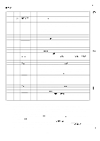
REV.-A Signal Return Signal Dir. Pin No. Pin No. Name 10 28 ACKNLG out 11 29 BUSY out 12 30 PE out 13 - - - 14 - AUTO FEED In XT 15 - NC - 16 - Ov - 17 - CHASSIS - GND 18 - NC - 9 to 30 - GND - 31 - INIT In 32 - ERROR out 33 - GND - 34 - NC - 35 - - - 36 - SLCT IN In (Continued) Description Approx.12 us pulse. LOW indicates that data has been received and that the printer is ready to accept more data. A HIGH signal indicates that the printer cannot receive more data. The signal becomes HIGH in the following cases: 1. During data entry 2. During input buffer full 3. During printer error status A HIGH signal indicates that the printer is out of paper. Pulled up to +5V through a 3.3 K-ohm resistor. When this signal is LOW, paper is automatically fed one line upon receipt of a CR code. (The signal level can be set LOW by default.) Not used. Logic GND level. Printer chassis GND. In the printer, the chassis GND and the logic GND are shortcircuited. Not used. TWISTED-PAIR RETURN signal GND level. When the level of this signal becomes LOW, the printer controller is reset to its initial state and the print buffer is cleared. This signal is normally atthe HIGH level, and its pulse width must be more than 50 ps at the receiving terminal. The level of this signal becomes LOW when the printer is in - 1. Paper-out status 2. Error status TWISTED-PAIR RETURN signal GND level. Not used. Pulled up to +5V through a 3.3 K-ohm resistor. The data between DC3 and DCI is invalid when this signal is HIGH. (The level of this signal is factory set to LOW.) . e..- .., ~. ~ {.-= . '. Notes: 1 ) Direction of signal flow is as viewed from the printer. 2) Return means TWISTED PAIR RETURN and is to be connected at signal ground level. 3) Be sure to use a twisted-pair cable for each signal and always complete connection on the return side. To prevent noise effectively, these cables should be shielded and connected to the chassis of the host computer and the printer, respectively. 4) All interface conditions are based on ITL level. Both the rise and fall times of each signal must be less than 0.2 VS. 5) Data transfer must not be carried out by ignoring the ACKNLG or BUSY signal. (Data transfer to this printer can be carried out only after confirming the ACKNLG signal or when . the level of the BUSY signal is LOW.) . :_ .,. 1-16
-
 1
1 -
2
-
3
-
4
-
5
-
6
-
7
-
8
-
9
-
10
-
11
-
12
-
13
-
14
-
15
-
16
-
17
-
18
-
19
-
 20
20 -
 21
21 -
 22
22 -
 23
23 -
 24
24 -
 25
25 -
 26
26 -
 27
27 -
 28
28 -
 29
29 -
 30
30 -
31
-
32
-
33
-
34
-
35
-
36
-
37
-
38
-
39
-
40
-
41
-
42
-
43
-
44
-
45
-
46
-
47
-
48
-
49
-
50
-
51
-
52
-
53
-
54
-
55
-
56
-
57
-
58
-
59
-
60
-
61
-
62
-
63
-
64
-
65
-
66
-
67
-
68
-
69
-
70
-
71
-
72
-
73
-
74
-
75
-
76
-
77
-
78
-
79
-
80
-
81
-
82
-
83
-
84
-
85
-
86
-
87
-
88
-
89
-
90
-
91
-
92
-
93
-
94
-
95
-
96
-
97
-
98
-
99
-
100
-
101
-
102
-
103
-
104
-
105
-
106
-
107
-
108
-
109
-
110
-
111
-
112
-
113
-
114
-
115
-
116
-
117
-
118
-
119
-
120
-
121
-
122
-
123
-
124
-
125
-
126
-
127
-
128
-
129
-
130
-
131
-
132
-
133
-
134
-
135
-
136
-
137
-
138
 |
 |
