Epson FX 1170 Service Manual - Page 79
Disassembly and Assembly, necessary.
 |
View all Epson FX 1170 manuals
Add to My Manuals
Save this manual to your list of manuals |
Page 79 highlights
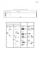
REV.-A 3.2 Disassembly and Assembly This section describes the procedures for disassembling and assembling the main components of the "" printer. In general, you can install a component in the printer by simply reversing the procedure for removing the component. Therefore, this chapter does not describe assembly procedures in most cases. If necessary, special notes on assembling or adjusting a component are given at the end of the description of each procedure. Be sure to follow the instructions in these notes. WARNING Before disassembling the printer, read the warning in Section3.1. CAUTION Before disassembling any part of the printer, remove the paper and the ink ribbon. Also disconnect the interface cable. .- Note: Exploded diagrams in the appendix show how the components fit together. Refer to them as L-=-, necessary. The flowchafi below shows the order in which you need to disassemble the printer. 1 START 1 Disconnect the printer's power cord and interface cable. I 1 EsEEl mm m -:-s $.. Figure 3-1. Flowchart for Disassembling the Printer 3-4
-
 1
1 -
2
-
3
-
4
-
5
-
6
-
7
-
8
-
9
-
10
-
11
-
12
-
13
-
14
-
15
-
16
-
17
-
18
-
19
-
20
-
21
-
22
-
23
-
24
-
25
-
26
-
27
-
28
-
29
-
30
-
31
-
32
-
33
-
34
-
35
-
36
-
37
-
38
-
39
-
40
-
41
-
42
-
43
-
44
-
45
-
46
-
47
-
48
-
49
-
50
-
51
-
52
-
53
-
54
-
55
-
56
-
57
-
58
-
59
-
60
-
61
-
62
-
63
-
64
-
65
-
66
-
67
-
68
-
69
-
70
-
71
-
72
-
73
-
 74
74 -
 75
75 -
 76
76 -
 77
77 -
 78
78 -
 79
79 -
 80
80 -
 81
81 -
 82
82 -
 83
83 -
 84
84 -
85
-
86
-
87
-
88
-
89
-
90
-
91
-
92
-
93
-
94
-
95
-
96
-
97
-
98
-
99
-
100
-
101
-
102
-
103
-
104
-
105
-
106
-
107
-
108
-
109
-
110
-
111
-
112
-
113
-
114
-
115
-
116
-
117
-
118
-
119
-
120
-
121
-
122
-
123
-
124
-
125
-
126
-
127
-
128
-
129
-
130
-
131
-
132
-
133
-
134
-
135
-
136
-
137
-
138
 |
 |
