Epson FX 1170 Service Manual - Page 75
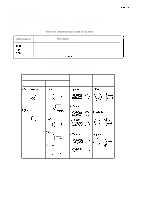
Connecting the FFC Cable to the Panel Unit, REV.-A, PIATEN, PSB/PSE
 |
View all Epson FX 1170 manuals
Add to My Manuals
Save this manual to your list of manuals |
Page 75 highlights
REV.-A LIST OF FIGURES Figure 3-1. Flowchart for Disassembling the Printer 3. -4 Figure 3-2. Removing the PAPER GUIDE ASSEMBLY 3-5 Figure 3-3. Removing the PANEL UNIT 3.6 Figure 3-4. Connecting the FFC Cable to the Panel Unit 3. -6 Figure 3-5. Removing the PRINTHEAD 3. -7 Figure 3-6. Removing the HOUSING ASSEMBLY, UPPER 3-8 Figure 3-7. Removing the PRINTER MECHANISM 3. -9 figure 3-8. Removing the PIATEN ASSEMBLY 3. -1o Figure 3-9. Removing the FRAME ASSEMBLY, REAR 3-11 Figure 3-10. Removing the MOTOR ASSEMBLY, CR 3. -12 Figure 3-11. Positioning the MOTOR ASSEMBLY, CR 3. -12 Figure 3-12. Removing the MOTOR ASSEMBLY, PF 3-13 Figure 3-13. Disassembling the GEAR TRAIN, PF 3. -14 Figure 3-14. Positioning the LEVER, RELEASE for Insertion 3-14 Figure 3-15. Removing the CARRIAGE GUIDE ASSEMBLY 3-15 Figure 3-16. Attaching the TIMING BELT 3. -16 Figure 3-17. Removing the RD ASSEMBLY 3-17 Figure 3-18. Removing the DETECTOR, HP 3. -18 Figure 3-19. Removing the DETECTOR, PG 3. -18 Figure 3-20. Removing the DETECTORS, PE 3. -19 Figure 3-21. Removing the DETECTOR, RELEASE 3. -20 Figure 3-22. Arranging the Cables 3. .-21 Figure 3-23. Disassembling the Tractor Unit 3. -22 Figure 3-24. Position of the Cog 3. .-22 Figure 3-25. Removing the BOARD ASSEMBLY, C084 MAIN 3-23 Figure 3-26. Removing the BOARD ASSEMBLY, C076 PSB/PSE 3-24 LIST OF TABLES '7 f -. ; Table 3-1. Recommended Toois 3. .-.1 Table 3-2. Equipment Required for Maintenance 3-l Table 3-3. Inspection Checklist for Repaired Printer 3. -2 Table 3-4. Abbreviations Used for Screws 3-3 Table 3-5. Screw Types and Abbreviations 3.3 S.ii
-
 1
1 -
2
-
3
-
4
-
5
-
6
-
7
-
8
-
9
-
10
-
11
-
12
-
13
-
14
-
15
-
16
-
17
-
18
-
19
-
20
-
21
-
22
-
23
-
24
-
25
-
26
-
27
-
28
-
29
-
30
-
31
-
32
-
33
-
34
-
35
-
36
-
37
-
38
-
39
-
40
-
41
-
42
-
43
-
44
-
45
-
46
-
47
-
48
-
49
-
50
-
51
-
52
-
53
-
54
-
55
-
56
-
57
-
58
-
59
-
60
-
61
-
62
-
63
-
64
-
65
-
66
-
67
-
68
-
69
-
 70
70 -
 71
71 -
 72
72 -
 73
73 -
 74
74 -
 75
75 -
 76
76 -
 77
77 -
 78
78 -
 79
79 -
 80
80 -
81
-
82
-
83
-
84
-
85
-
86
-
87
-
88
-
89
-
90
-
91
-
92
-
93
-
94
-
95
-
96
-
97
-
98
-
99
-
100
-
101
-
102
-
103
-
104
-
105
-
106
-
107
-
108
-
109
-
110
-
111
-
112
-
113
-
114
-
115
-
116
-
117
-
118
-
119
-
120
-
121
-
122
-
123
-
124
-
125
-
126
-
127
-
128
-
129
-
130
-
131
-
132
-
133
-
134
-
135
-
136
-
137
-
138
 |
 |
