Epson FX 1170 Service Manual - Page 24
Interface, 3.1 Parallel Interface
 |
View all Epson FX 1170 manuals
Add to My Manuals
Save this manual to your list of manuals |
Page 24 highlights
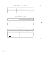
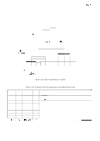
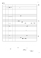
, 1.3 Interface This printer has a built-in, 8-bit centronics parallel interface. 1.3.1 Parallel Interface Data transmission mode Synchronization Handshaking Logic level Connector plug 8-bit parallel Controlled by external STROBE pulse. Controlled by ACKNLG and BUSY signals. ITL- compatible 57-30360 (Amphenol) or equivalent It is recommended that the interface cable be as short as possible (10 feet maximum). REV.-A DATA STROBE tl tl tl t2 t3 tl : 0.5 us (min.) t2: 7 us (approx.) t3: 5 us (approx.) Figure 1-6. Data Transmission Timing Table 1-14. Connector Pin Assignments and Signal Functions Signal Return Pin No. Pin No. 1 19 Signal Name STROBE 2 20 DATA 1 3 21 DATA 2 4 22 DATA 3 5 23 DATA 4 6 24 DATA 5 7 25 DATA 6 8 26 DATA 7 Dir. Description In STROBE pulse to read data in. Pulse width must be more than 0.5 Bs at receiving terminal. In These signals represent the 1st to 8th bits of parallel data, In respectively. Each signal is HIGH when data is a logical 1 and In LOW when a logical O. In In In In 1-15
-
 1
1 -
2
-
3
-
4
-
5
-
6
-
7
-
8
-
9
-
10
-
11
-
12
-
13
-
14
-
15
-
16
-
17
-
18
-
 19
19 -
 20
20 -
 21
21 -
 22
22 -
 23
23 -
 24
24 -
 25
25 -
 26
26 -
 27
27 -
 28
28 -
 29
29 -
30
-
31
-
32
-
33
-
34
-
35
-
36
-
37
-
38
-
39
-
40
-
41
-
42
-
43
-
44
-
45
-
46
-
47
-
48
-
49
-
50
-
51
-
52
-
53
-
54
-
55
-
56
-
57
-
58
-
59
-
60
-
61
-
62
-
63
-
64
-
65
-
66
-
67
-
68
-
69
-
70
-
71
-
72
-
73
-
74
-
75
-
76
-
77
-
78
-
79
-
80
-
81
-
82
-
83
-
84
-
85
-
86
-
87
-
88
-
89
-
90
-
91
-
92
-
93
-
94
-
95
-
96
-
97
-
98
-
99
-
100
-
101
-
102
-
103
-
104
-
105
-
106
-
107
-
108
-
109
-
110
-
111
-
112
-
113
-
114
-
115
-
116
-
117
-
118
-
119
-
120
-
121
-
122
-
123
-
124
-
125
-
126
-
127
-
128
-
129
-
130
-
131
-
132
-
133
-
134
-
135
-
136
-
137
-
138
 |
 |
