Epson Stylus Pro User Manual - Page 74
Interface Specifications, Parallel Interface
 |
View all Epson Stylus Pro manuals
Add to My Manuals
Save this manual to your list of manuals |
Page 74 highlights
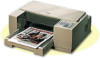
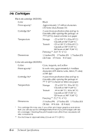
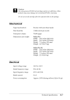
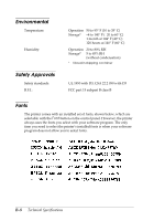
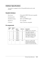
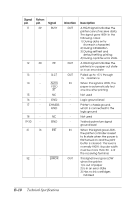
Interface Specifications Your printer is equipped with an 8-bit parallel interface and a serial interface. Parallel Interface Data format: Synchronization: Handshake timing: Signal level: Connector: 8-bit parallel, IEEE P1284 mode compatible STROBE pulse BUSY and ACKNLG signals TTL compatible 36-pin, Centronics compatible Pin assignments Signal pin 1 2 3 4 5 6 7 8 9 10 Return pin 19 20 21 22 23 24 25 26 27 28 Signal STROBE DATA 1 DATA 2 DATA 3 DATA 4 DATA 5 DATA 6 DATA 7 DATA 8 ACKNLG Direction IN IN IN IN IN IN IN IN IN OUT Description STROBE pulse to read data. These signals represent information in bits 0 to 7 of parallel data respectively. Each signal is at HIGH level when data is logical 1 and LOW when it is logical 0. About a 5-µs pulse. LOW indicates data has been received and the printer is ready to accept more data. Technical Specifications B-9
-
 1
1 -
2
-
3
-
4
-
5
-
6
-
7
-
8
-
9
-
10
-
11
-
12
-
13
-
14
-
15
-
16
-
17
-
18
-
19
-
20
-
21
-
22
-
23
-
24
-
25
-
26
-
27
-
28
-
29
-
30
-
31
-
32
-
33
-
34
-
35
-
36
-
37
-
38
-
39
-
40
-
41
-
42
-
43
-
44
-
45
-
46
-
47
-
48
-
49
-
50
-
51
-
52
-
53
-
54
-
55
-
56
-
57
-
58
-
59
-
60
-
61
-
62
-
63
-
64
-
65
-
66
-
67
-
68
-
 69
69 -
 70
70 -
 71
71 -
 72
72 -
 73
73 -
 74
74 -
 75
75 -
 76
76 -
 77
77 -
 78
78 -
 79
79 -
80
-
81
-
82
-
83
-
84
-
85
-
86
-
87
-
88
-
89
-
90
-
91
-
92
-
93
-
94
-
95
-
96
-
97
-
98
 |
 |