Garmin G3X Pilots Guide - Page 112
When unsafe operating conditions, bands indicate caution and warning, respectively.
 |
View all Garmin G3X manuals
Add to My Manuals
Save this manual to your list of manuals |
Page 112 highlights
Overview System Instruments Flight EIS CNS Interface GPS Navigation EIS 24 25 26 23 27 28 22 21 29 30 20 19 18 31 17 Example Engine (ENG) Page Configuration (Full-Screen MFD) Green bands on the instruments indicate normal ranges of operation; yellow and red bands indicate caution and warning, respectively. When unsafe operating conditions occur, the corresponding caution readout will display solid yellow and the warning readout will flash red. If sensory data to an instrument becomes invalid or unavailable, a red "X" is displayed across the instrument. Flight Planning Hazard Avoidance Additional Features Integrated Autopilot Annun/Alerts Appendix Index 94 Garmin G3X Pilot's Guide 190-01115-00 Rev. F
-
 1
1 -
2
-
3
-
4
-
5
-
6
-
7
-
8
-
9
-
10
-
11
-
12
-
13
-
14
-
15
-
16
-
17
-
18
-
19
-
20
-
21
-
22
-
23
-
24
-
25
-
26
-
27
-
28
-
29
-
30
-
31
-
32
-
33
-
34
-
35
-
36
-
37
-
38
-
39
-
40
-
41
-
42
-
43
-
44
-
45
-
46
-
47
-
48
-
49
-
50
-
51
-
52
-
53
-
54
-
55
-
56
-
57
-
58
-
59
-
60
-
61
-
62
-
63
-
64
-
65
-
66
-
67
-
68
-
69
-
70
-
71
-
72
-
73
-
74
-
75
-
76
-
77
-
78
-
79
-
80
-
81
-
82
-
83
-
84
-
85
-
86
-
87
-
88
-
89
-
90
-
91
-
92
-
93
-
94
-
95
-
96
-
97
-
98
-
99
-
100
-
101
-
102
-
103
-
104
-
105
-
106
-
 107
107 -
 108
108 -
 109
109 -
 110
110 -
 111
111 -
 112
112 -
 113
113 -
 114
114 -
 115
115 -
 116
116 -
 117
117 -
118
-
119
-
120
-
121
-
122
-
123
-
124
-
125
-
126
-
127
-
128
-
129
-
130
-
131
-
132
-
133
-
134
-
135
-
136
-
137
-
138
-
139
-
140
-
141
-
142
-
143
-
144
-
145
-
146
-
147
-
148
-
149
-
150
-
151
-
152
-
153
-
154
-
155
-
156
-
157
-
158
-
159
-
160
-
161
-
162
-
163
-
164
-
165
-
166
-
167
-
168
-
169
-
170
-
171
-
172
-
173
-
174
-
175
-
176
-
177
-
178
-
179
-
180
-
181
-
182
-
183
-
184
-
185
-
186
-
187
-
188
-
189
-
190
-
191
-
192
-
193
-
194
-
195
-
196
-
197
-
198
-
199
-
200
-
201
-
202
-
203
-
204
-
205
-
206
-
207
-
208
-
209
-
210
-
211
-
212
-
213
-
214
-
215
-
216
-
217
-
218
-
219
-
220
-
221
-
222
-
223
-
224
-
225
-
226
-
227
-
228
-
229
-
230
-
231
-
232
-
233
-
234
-
235
-
236
-
237
-
238
-
239
-
240
-
241
-
242
-
243
-
244
-
245
-
246
-
247
-
248
-
249
-
250
-
251
-
252
-
253
-
254
-
255
-
256
-
257
-
258
-
259
-
260
-
261
-
262
-
263
-
264
-
265
-
266
-
267
-
268
-
269
-
270
-
271
-
272
-
273
-
274
-
275
-
276
-
277
-
278
-
279
-
280
-
281
-
282
-
283
-
284
-
285
-
286
-
287
-
288
-
289
-
290
-
291
-
292
-
293
-
294
-
295
-
296
-
297
-
298
-
299
-
300
-
301
-
302
-
303
-
304
-
305
-
306
-
307
-
308
-
309
-
310
-
311
-
312
-
313
-
314
-
315
-
316
-
317
-
318
-
319
-
320
-
321
-
322
-
323
-
324
-
325
-
326
-
327
-
328
-
329
-
330
-
331
-
332
-
333
-
334
-
335
-
336
-
337
-
338
-
339
-
340
-
341
-
342
-
343
-
344
-
345
-
346
-
347
-
348
-
349
-
350
-
351
-
352
-
353
-
354
-
355
-
356
-
357
-
358
-
359
-
360
-
361
-
362
-
363
-
364
-
365
-
366
-
367
-
368
-
369
-
370
-
371
-
372
 |
 |

Garmin G3X Pilot’s Guide
190-01115-00
Rev. F
94
EIS
System
Overview
Flight
Instruments
EIS
CNS
Interface
GPS
Navigation
Flight
Planning
Hazard
Avoidance
Additional
Features
Integrated
Autopilot
Annun/Alerts
Appendix
Index
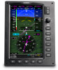
Example Engine (ENG) Page Configuration
(Full-Screen MFD)
23
25
27
21
28
17
31
30
18
19
20
29
26
22
24
Green bands on the instruments indicate normal ranges of operation; yellow and red
bands indicate caution and warning, respectively.
When unsafe operating conditions
occur, the corresponding caution readout will display solid yellow and the warning
readout will flash red.
If sensory data to an instrument becomes invalid or unavailable,
a red “X” is displayed across the instrument.