Garmin G3X Pilots Guide - Page 93
COURSE DEVIATION INDICATOR CDI, The HSI contains a Course Deviation Indicator CDI
 |
View all Garmin G3X manuals
Add to My Manuals
Save this manual to your list of manuals |
Page 93 highlights
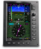
System Overview Flight Instruments EIS Flight Instruments Enabling/disabling the bearing pointer and changing sources: 1) From the full screen PFD and/or split screen PFD Page, press the MENU Key. 2) Move the FMS Joystick to highlight the desired Bearing Pointer. 3) Turn the FMS Joystick to highlight the desired source (dependant on the external navigators configured), or to remove the bearing pointer and information window, highlight 'Off'. COURSE DEVIATION INDICATOR (CDI) The HSI contains a Course Deviation Indicator (CDI), with a Course Pointer, To/From Indicator, and a sliding deviation bar and scale. The course pointer is a single line arrow (GPS1, VOR1, and LOC1) or a double line arrow (GPS2, VOR2, and LOC2) which points in the direction of the set course. The To/From arrow rotates with the course pointer and is displayed when the active NAVAID is received. The Course Deviation Indicator (CDI) moves left or right from the course pointer along a lateral deviation scale to display aircraft position relative to the course. If the course deviation data is not valid, the CDI is not displayed. Another Lateral Deviation Scale and combination Course Deviation and To-From Indicator is located below the slip/skid indicator. CNS Interface GPS Navigation Flight Planning Hazard Avoidance Additional Features Integrated Autopilot Annun/Alerts Course Deviation & To/From Indicator Lateral Deviation Scale Lateral Deviation Scale The CDI is capable of displaying two sources of navigation: GPS or NAV (VOR, localizer) depending on the external navigator(s) configured (refer to the G3X Installation Manual for more information). Color indicates the current navigation source: magenta (for GPS) or green (for VOR and LOC). The full-scale limits for the CDI are defined by a GPS-derived distance when coupled to GPS. When coupled to a VOR or localizer (LOC), the CDI has the same angular limits as a mechanical CDI. If the CDI exceeds the maximum deviation on the scale (two dots) while coupled to GPS, the crosstrack error (XTK) is displayed below the white aircraft symbol. Appendix Index 190-01115-00 Rev. F Garmin G3X Pilot's Guide 75
-
 1
1 -
2
-
3
-
4
-
5
-
6
-
7
-
8
-
9
-
10
-
11
-
12
-
13
-
14
-
15
-
16
-
17
-
18
-
19
-
20
-
21
-
22
-
23
-
24
-
25
-
26
-
27
-
28
-
29
-
30
-
31
-
32
-
33
-
34
-
35
-
36
-
37
-
38
-
39
-
40
-
41
-
42
-
43
-
44
-
45
-
46
-
47
-
48
-
49
-
50
-
51
-
52
-
53
-
54
-
55
-
56
-
57
-
58
-
59
-
60
-
61
-
62
-
63
-
64
-
65
-
66
-
67
-
68
-
69
-
70
-
71
-
72
-
73
-
74
-
75
-
76
-
77
-
78
-
79
-
80
-
81
-
82
-
83
-
84
-
85
-
86
-
87
-
 88
88 -
 89
89 -
 90
90 -
 91
91 -
 92
92 -
 93
93 -
 94
94 -
 95
95 -
 96
96 -
 97
97 -
 98
98 -
99
-
100
-
101
-
102
-
103
-
104
-
105
-
106
-
107
-
108
-
109
-
110
-
111
-
112
-
113
-
114
-
115
-
116
-
117
-
118
-
119
-
120
-
121
-
122
-
123
-
124
-
125
-
126
-
127
-
128
-
129
-
130
-
131
-
132
-
133
-
134
-
135
-
136
-
137
-
138
-
139
-
140
-
141
-
142
-
143
-
144
-
145
-
146
-
147
-
148
-
149
-
150
-
151
-
152
-
153
-
154
-
155
-
156
-
157
-
158
-
159
-
160
-
161
-
162
-
163
-
164
-
165
-
166
-
167
-
168
-
169
-
170
-
171
-
172
-
173
-
174
-
175
-
176
-
177
-
178
-
179
-
180
-
181
-
182
-
183
-
184
-
185
-
186
-
187
-
188
-
189
-
190
-
191
-
192
-
193
-
194
-
195
-
196
-
197
-
198
-
199
-
200
-
201
-
202
-
203
-
204
-
205
-
206
-
207
-
208
-
209
-
210
-
211
-
212
-
213
-
214
-
215
-
216
-
217
-
218
-
219
-
220
-
221
-
222
-
223
-
224
-
225
-
226
-
227
-
228
-
229
-
230
-
231
-
232
-
233
-
234
-
235
-
236
-
237
-
238
-
239
-
240
-
241
-
242
-
243
-
244
-
245
-
246
-
247
-
248
-
249
-
250
-
251
-
252
-
253
-
254
-
255
-
256
-
257
-
258
-
259
-
260
-
261
-
262
-
263
-
264
-
265
-
266
-
267
-
268
-
269
-
270
-
271
-
272
-
273
-
274
-
275
-
276
-
277
-
278
-
279
-
280
-
281
-
282
-
283
-
284
-
285
-
286
-
287
-
288
-
289
-
290
-
291
-
292
-
293
-
294
-
295
-
296
-
297
-
298
-
299
-
300
-
301
-
302
-
303
-
304
-
305
-
306
-
307
-
308
-
309
-
310
-
311
-
312
-
313
-
314
-
315
-
316
-
317
-
318
-
319
-
320
-
321
-
322
-
323
-
324
-
325
-
326
-
327
-
328
-
329
-
330
-
331
-
332
-
333
-
334
-
335
-
336
-
337
-
338
-
339
-
340
-
341
-
342
-
343
-
344
-
345
-
346
-
347
-
348
-
349
-
350
-
351
-
352
-
353
-
354
-
355
-
356
-
357
-
358
-
359
-
360
-
361
-
362
-
363
-
364
-
365
-
366
-
367
-
368
-
369
-
370
-
371
-
372
 |
 |
