HP 2605 Service Manual - Page 68
Main motor failure detection - drum
 |
View all HP 2605 manuals
Add to My Manuals
Save this manual to your list of manuals |
Page 68 highlights
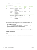
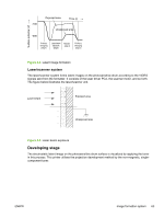
The specifications of each motor are listed in the following table. Table 4-2 Motor specifications Name Motor Purpose Type Main motor (M1) Drive ETB belt, photosensitive drum and developing cylinder DC motor Fuser/delivery motor (M2) Drive fuser pressure roller, delivery roller and automatic release of fuser pressure Stepping motor Pickup motor (M3) Drive pickup roller and registration roller Stepping motor Fan (FM1) Circulate air around cartridge DC motor Direction of rotation CW CW/CCW CW - Failure detection Yes No No Yes Main motor failure detection The CPU determines the main motor failure, stops the printer, and notifies the formatter of error status, when it encounters the following conditions. ● Main motor start-up abnormality The interval of the MAIN MOTOR SPEED DETECTION signal (/MAINMFG) does not become the specified interval after 1000 ms of the main motor drive start. ● Main motor rotation abnormality The interval of the /MAINMFG signal stays at an irregular interval for 100 ms and longer after once it has become the specified interval. Fan motor failure detection The CPU determines the fan motor failure and notifies the formatter when it encounters the following condition. The FAN LOCK signal (FANLCK) is "H" for approximately 10 seconds and longer during fan motor rotation. 58 Chapter 4 Operational theory ENWW
-
 1
1 -
2
-
3
-
4
-
5
-
6
-
7
-
8
-
9
-
10
-
11
-
12
-
13
-
14
-
15
-
16
-
17
-
18
-
19
-
20
-
21
-
22
-
23
-
24
-
25
-
26
-
27
-
28
-
29
-
30
-
31
-
32
-
33
-
34
-
35
-
36
-
37
-
38
-
39
-
40
-
41
-
42
-
43
-
44
-
45
-
46
-
47
-
48
-
49
-
50
-
51
-
52
-
53
-
54
-
55
-
56
-
57
-
58
-
59
-
60
-
61
-
62
-
 63
63 -
 64
64 -
 65
65 -
 66
66 -
 67
67 -
 68
68 -
 69
69 -
 70
70 -
 71
71 -
 72
72 -
 73
73 -
74
-
75
-
76
-
77
-
78
-
79
-
80
-
81
-
82
-
83
-
84
-
85
-
86
-
87
-
88
-
89
-
90
-
91
-
92
-
93
-
94
-
95
-
96
-
97
-
98
-
99
-
100
-
101
-
102
-
103
-
104
-
105
-
106
-
107
-
108
-
109
-
110
-
111
-
112
-
113
-
114
-
115
-
116
-
117
-
118
-
119
-
120
-
121
-
122
-
123
-
124
-
125
-
126
-
127
-
128
-
129
-
130
-
131
-
132
-
133
-
134
-
135
-
136
-
137
-
138
-
139
-
140
-
141
-
142
-
143
-
144
-
145
-
146
-
147
-
148
-
149
-
150
-
151
-
152
-
153
-
154
-
155
-
156
-
157
-
158
-
159
-
160
-
161
-
162
-
163
-
164
-
165
-
166
-
167
-
168
-
169
-
170
-
171
-
172
-
173
-
174
-
175
-
176
-
177
-
178
-
179
-
180
-
181
-
182
-
183
-
184
-
185
-
186
-
187
-
188
-
189
-
190
-
191
-
192
-
193
-
194
-
195
-
196
-
197
-
198
-
199
-
200
-
201
-
202
-
203
-
204
-
205
-
206
-
207
-
208
-
209
-
210
-
211
-
212
-
213
-
214
-
215
-
216
-
217
-
218
-
219
-
220
-
221
-
222
-
223
-
224
-
225
-
226
-
227
-
228
-
229
-
230
-
231
-
232
-
233
-
234
-
235
-
236
-
237
-
238
-
239
-
240
-
241
-
242
-
243
-
244
-
245
-
246
-
247
-
248
-
249
-
250
-
251
-
252
-
253
-
254
-
255
-
256
-
257
-
258
-
259
-
260
-
261
-
262
-
263
-
264
-
265
-
266
-
267
-
268
 |
 |
