HP 2605 Service Manual - Page 83
Solenoid, motor, and fan locations, Printed circuit assembly locations,
 |
View all HP 2605 manuals
Add to My Manuals
Save this manual to your list of manuals |
Page 83 highlights
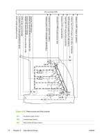
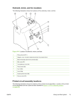
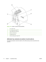
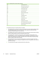
Solenoid, motor, and fan locations The following illustration shows the locations of the solenoids, motor, and fan. Figure 4-14 Location of solenoids, motors, and fans 1 Pickup solenoid (SL1) 2 Magenta, cyan, and yellow developing cylinder drive solenoid (SL2) 3 Black developing cylinder drive solenoid (SL3) 4 Main motor (M1) 5 Fusing/delivery motor (M2) 6 Pickup motor (M3) 7 Fan 1 (FM1) 8 Fan 2 (FM2) 9 Duplexing feed motor (M6) 10 Reverse motor (M7) Printed circuit assembly locations The following illustration shows the locations of the printed circuit assemblies. Location of the printed circuit assemblies and list of parts are also identified in Figure 7-15 PCA assembly location on page 208. ENWW Pickup and feed system 73
-
 1
1 -
2
-
3
-
4
-
5
-
6
-
7
-
8
-
9
-
10
-
11
-
12
-
13
-
14
-
15
-
16
-
17
-
18
-
19
-
20
-
21
-
22
-
23
-
24
-
25
-
26
-
27
-
28
-
29
-
30
-
31
-
32
-
33
-
34
-
35
-
36
-
37
-
38
-
39
-
40
-
41
-
42
-
43
-
44
-
45
-
46
-
47
-
48
-
49
-
50
-
51
-
52
-
53
-
54
-
55
-
56
-
57
-
58
-
59
-
60
-
61
-
62
-
63
-
64
-
65
-
66
-
67
-
68
-
69
-
70
-
71
-
72
-
73
-
74
-
75
-
76
-
77
-
 78
78 -
 79
79 -
 80
80 -
 81
81 -
 82
82 -
 83
83 -
 84
84 -
 85
85 -
 86
86 -
 87
87 -
 88
88 -
89
-
90
-
91
-
92
-
93
-
94
-
95
-
96
-
97
-
98
-
99
-
100
-
101
-
102
-
103
-
104
-
105
-
106
-
107
-
108
-
109
-
110
-
111
-
112
-
113
-
114
-
115
-
116
-
117
-
118
-
119
-
120
-
121
-
122
-
123
-
124
-
125
-
126
-
127
-
128
-
129
-
130
-
131
-
132
-
133
-
134
-
135
-
136
-
137
-
138
-
139
-
140
-
141
-
142
-
143
-
144
-
145
-
146
-
147
-
148
-
149
-
150
-
151
-
152
-
153
-
154
-
155
-
156
-
157
-
158
-
159
-
160
-
161
-
162
-
163
-
164
-
165
-
166
-
167
-
168
-
169
-
170
-
171
-
172
-
173
-
174
-
175
-
176
-
177
-
178
-
179
-
180
-
181
-
182
-
183
-
184
-
185
-
186
-
187
-
188
-
189
-
190
-
191
-
192
-
193
-
194
-
195
-
196
-
197
-
198
-
199
-
200
-
201
-
202
-
203
-
204
-
205
-
206
-
207
-
208
-
209
-
210
-
211
-
212
-
213
-
214
-
215
-
216
-
217
-
218
-
219
-
220
-
221
-
222
-
223
-
224
-
225
-
226
-
227
-
228
-
229
-
230
-
231
-
232
-
233
-
234
-
235
-
236
-
237
-
238
-
239
-
240
-
241
-
242
-
243
-
244
-
245
-
246
-
247
-
248
-
249
-
250
-
251
-
252
-
253
-
254
-
255
-
256
-
257
-
258
-
259
-
260
-
261
-
262
-
263
-
264
-
265
-
266
-
267
-
268
 |
 |
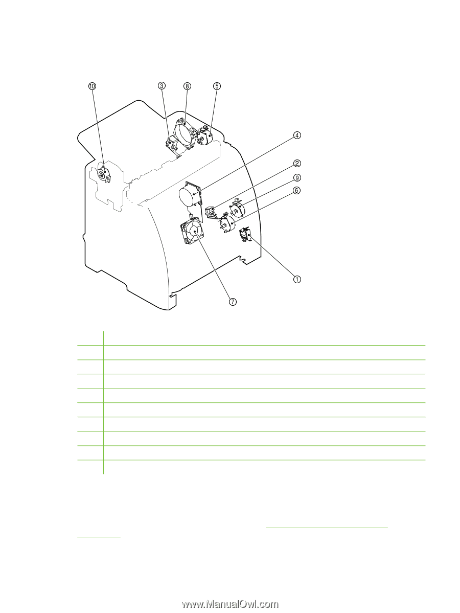
Solenoid, motor, and fan locations
The following illustration shows the locations of the solenoids, motor, and fan.
Figure 4-14
Location of solenoids, motors, and fans
1
Pickup solenoid (SL1)
2
Magenta, cyan, and yellow developing cylinder drive solenoid (SL2)
3
Black developing cylinder drive solenoid (SL3)
4
Main motor (M1)
5
Fusing/delivery motor (M2)
6
Pickup motor (M3)
7
Fan 1 (FM1)
8
Fan 2 (FM2)
9
Duplexing feed motor (M6)
10
Reverse motor (M7)
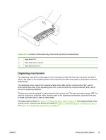
Printed circuit assembly locations
The following illustration shows the locations of the printed circuit assemblies. Location of the printed
circuit assemblies and list of parts are also identified in
Figure
7
-
15
PCA
assembly
location
on
page
208
.
ENWW
Pickup and feed system
73