HP 2605 Service Manual - Page 88
The duplexing driver stops the reverse motor and turns off the reverse solenoid after the trailing
 |
View all HP 2605 manuals
Add to My Manuals
Save this manual to your list of manuals |
Page 88 highlights
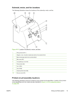
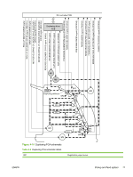
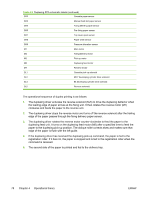
Table 4-3 Duplexing PCA schematic labels (continued) SR2 Cassette paper sensor SR3 Manual feed slot paper sensor SR4 Fixing delivery paper sensor SR5 Pre-fixing paper sensor SR7 Top cover open sensor SR8 Paper width sensor SR9 Pressure alienation sensor M1 Main motor M2 Fixing/delivery motor M3 Pick-up motor M6 Duplexing feed motor M7 Reverse motor SL1 Cassette pick-up solenoid SL2 MCY developing cylinder drive solenoid SL3 Bk developing cylinder drive solenoid SL5 Reverse solenoid The operational sequence of duplex printing is as follows: 1. The duplexing driver activates the reverse solenoid (SL5) to drive the duplexing deflector when the leading edge of paper arrives at the fixing unit. It then rotates the reverse motor (M7) clockwise and feeds the paper to the reverse unit. 2. The duplexing driver stops the reverse motor and turns off the reverse solenoid after the trailing edge of the paper passes through the fixing delivery paper sensor. 3. The duplexing driver rotates the reverse motor counter-clockwise to feed the paper to the duplexing feed unit. It turns on the duplexing feed motor (M6) after a specified time to feed the paper to the duplexing pick-up position. The oblique roller corrects skew and makes sure that edge of the paper is flush with the left guide. 4. If the duplexing driver has received the duplexing pick-up command, the paper is fed to the registration roller. If it has not, the paper is stopped and is fed to the registration roller when the command is received. 5. The second side of the paper is printed and fed to the delivery tray. 78 Chapter 4 Operational theory ENWW
-
 1
1 -
2
-
3
-
4
-
5
-
6
-
7
-
8
-
9
-
10
-
11
-
12
-
13
-
14
-
15
-
16
-
17
-
18
-
19
-
20
-
21
-
22
-
23
-
24
-
25
-
26
-
27
-
28
-
29
-
30
-
31
-
32
-
33
-
34
-
35
-
36
-
37
-
38
-
39
-
40
-
41
-
42
-
43
-
44
-
45
-
46
-
47
-
48
-
49
-
50
-
51
-
52
-
53
-
54
-
55
-
56
-
57
-
58
-
59
-
60
-
61
-
62
-
63
-
64
-
65
-
66
-
67
-
68
-
69
-
70
-
71
-
72
-
73
-
74
-
75
-
76
-
77
-
78
-
79
-
80
-
81
-
82
-
 83
83 -
 84
84 -
 85
85 -
 86
86 -
 87
87 -
 88
88 -
 89
89 -
 90
90 -
 91
91 -
 92
92 -
 93
93 -
94
-
95
-
96
-
97
-
98
-
99
-
100
-
101
-
102
-
103
-
104
-
105
-
106
-
107
-
108
-
109
-
110
-
111
-
112
-
113
-
114
-
115
-
116
-
117
-
118
-
119
-
120
-
121
-
122
-
123
-
124
-
125
-
126
-
127
-
128
-
129
-
130
-
131
-
132
-
133
-
134
-
135
-
136
-
137
-
138
-
139
-
140
-
141
-
142
-
143
-
144
-
145
-
146
-
147
-
148
-
149
-
150
-
151
-
152
-
153
-
154
-
155
-
156
-
157
-
158
-
159
-
160
-
161
-
162
-
163
-
164
-
165
-
166
-
167
-
168
-
169
-
170
-
171
-
172
-
173
-
174
-
175
-
176
-
177
-
178
-
179
-
180
-
181
-
182
-
183
-
184
-
185
-
186
-
187
-
188
-
189
-
190
-
191
-
192
-
193
-
194
-
195
-
196
-
197
-
198
-
199
-
200
-
201
-
202
-
203
-
204
-
205
-
206
-
207
-
208
-
209
-
210
-
211
-
212
-
213
-
214
-
215
-
216
-
217
-
218
-
219
-
220
-
221
-
222
-
223
-
224
-
225
-
226
-
227
-
228
-
229
-
230
-
231
-
232
-
233
-
234
-
235
-
236
-
237
-
238
-
239
-
240
-
241
-
242
-
243
-
244
-
245
-
246
-
247
-
248
-
249
-
250
-
251
-
252
-
253
-
254
-
255
-
256
-
257
-
258
-
259
-
260
-
261
-
262
-
263
-
264
-
265
-
266
-
267
-
268
 |
 |