HP 8100 Maintenance and Service Guide: HP Compaq 8100 and 8180 Elite Business - Page 122
Cable Connections, Drives, Drive Positions, CAUTION,
 |
View all HP 8100 manuals
Add to My Manuals
Save this manual to your list of manuals |
Page 122 highlights
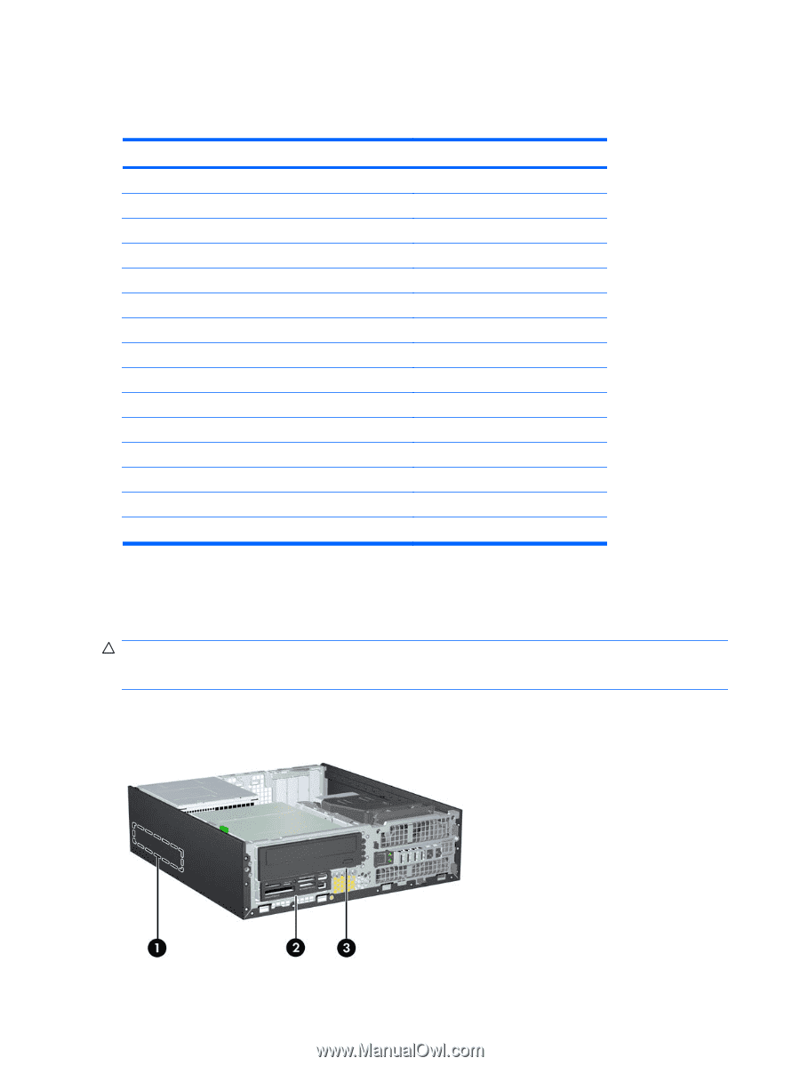
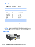
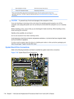
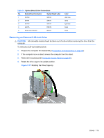
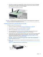
Cable Connections System board connectors are color-coded to make it easier to find the proper connection. System Board Connector Connector Color P1 White PWRCPU (P2) White SATA PWR1 (P160) Black CHFAN (P9) Brown PB/LED (P5) Black FRONT USB (P24) Yellow FRONT USB2 (P25) Green FRONT AUD (P23) Blue SPKR (P5) White COMB (P52) Black HLCK (P124) Black HSENSE (P125) White MEDIA (P150) Black MEDIA2 (P151) Black PAR (P126) Black Description Power supply, 6-pin Power supply, 4-pin SATA drive power connector Chassis fan Front power button/LED Front I/O USB Front I/O USB Front audio Internal speaker Serial port Hood lock solenoid Hood sensor Media card reader Media card reader Flying parallel port Drives A Torx T-15 screwdriver is needed to remove and install the guide screws on a drive. CAUTION: Make sure personal files on the hard drive are backed up to an external storage device before removing the hard drive. Failure to do so will result in data loss. After replacing the primary hard drive, you will need to run the Restore Plus! CD to load the HP factory-installed files. Drive Positions Figure 7-24 Drive Positions 112 Chapter 7 Removal and Replacement Procedures Small Form Factor (SFF) Chassis
-
 1
1 -
2
-
3
-
4
-
5
-
6
-
7
-
8
-
9
-
10
-
11
-
12
-
13
-
14
-
15
-
16
-
17
-
18
-
19
-
20
-
21
-
22
-
23
-
24
-
25
-
26
-
27
-
28
-
29
-
30
-
31
-
32
-
33
-
34
-
35
-
36
-
37
-
38
-
39
-
40
-
41
-
42
-
43
-
44
-
45
-
46
-
47
-
48
-
49
-
50
-
51
-
52
-
53
-
54
-
55
-
56
-
57
-
58
-
59
-
60
-
61
-
62
-
63
-
64
-
65
-
66
-
67
-
68
-
69
-
70
-
71
-
72
-
73
-
74
-
75
-
76
-
77
-
78
-
79
-
80
-
81
-
82
-
83
-
84
-
85
-
86
-
87
-
88
-
89
-
90
-
91
-
92
-
93
-
94
-
95
-
96
-
97
-
98
-
99
-
100
-
101
-
102
-
103
-
104
-
105
-
106
-
107
-
108
-
109
-
110
-
111
-
112
-
113
-
114
-
115
-
116
-
 117
117 -
 118
118 -
 119
119 -
 120
120 -
 121
121 -
 122
122 -
 123
123 -
 124
124 -
 125
125 -
 126
126 -
 127
127 -
128
-
129
-
130
-
131
-
132
-
133
-
134
-
135
-
136
-
137
-
138
-
139
-
140
-
141
-
142
-
143
-
144
-
145
-
146
-
147
-
148
-
149
-
150
-
151
-
152
-
153
-
154
-
155
-
156
-
157
-
158
-
159
-
160
-
161
-
162
-
163
-
164
-
165
-
166
-
167
-
168
-
169
-
170
-
171
-
172
-
173
-
174
-
175
-
176
-
177
-
178
-
179
-
180
-
181
-
182
-
183
-
184
-
185
-
186
-
187
-
188
-
189
-
190
-
191
-
192
-
193
-
194
-
195
-
196
-
197
-
198
-
199
-
200
-
201
-
202
-
203
-
204
-
205
-
206
-
207
-
208
-
209
-
210
-
211
-
212
-
213
-
214
-
215
-
216
-
217
-
218
-
219
-
220
-
221
-
222
-
223
-
224
-
225
-
226
-
227
-
228
-
229
-
230
-
231
-
232
-
233
-
234
-
235
-
236
-
237
-
238
-
239
-
240
-
241
-
242
-
243
-
244
-
245
-
246
-
247
-
248
 |
 |