HP 8100 Maintenance and Service Guide: HP Compaq 8100 and 8180 Elite Business - Page 131
Installing a Drive into the 3.5-inch External Drive Bay, CAUTION,
 |
View all HP 8100 manuals
Add to My Manuals
Save this manual to your list of manuals |
Page 131 highlights
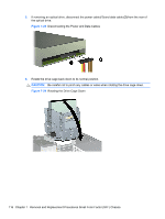
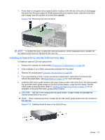
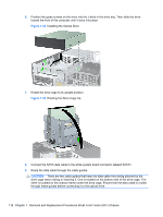
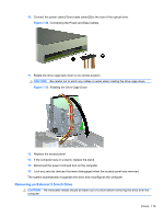
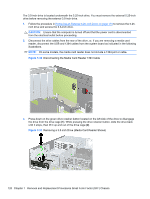
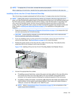
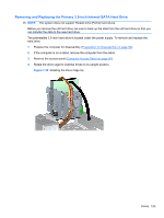
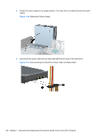
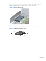
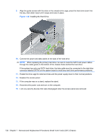
NOTE: To replace the 3.5-inch drive, reverse the removal procedure. When replacing a 3.5-inch drive, transfer the four guide screws from the old drive to the new one. Installing a Drive into the 3.5-inch External Drive Bay The 3.5-inch bay is located underneath the 5.25-inch drive. To install a drive into the 3.5-inch bay: NOTE: Install guide screws to ensure the drive will line up correctly in the drive cage and lock in place. HP has provided extra guide screws for the external drive bays (four 6-32 standard screws and four M3 metric screws), installed in the front of the chassis, under the front bezel. A secondary hard drive uses 6-32 standard screws. All other drives (except the primary hard drive) use M3 metric screws. The HP-supplied M3 metric screws are black and the HP-supplied 6-32 standard screws are silver. Refer to Installing and Removing Drives on page 113 for illustrations of the guide screw locations. 1. Follow the procedure in Removing an External 5.25-inch Drive on page 115 to remove the 5.25- inch drive and access the 3.5-inch drive bay. CAUTION: Ensure that the computer is turned off and that the power cord is disconnected from the electrical outlet before proceeding. 2. If you are installing a drive in a bay covered by a bezel blank, remove the front bezel then remove the bezel blank. See Bezel Blanks on page 101 for more information. 3. Position the guide screws on the drive into the J-slots in the drive bay. Then slide the drive toward the front of the computer until it locks into place. Figure 7-38 Installing a Drive into the 3.5-inch Drive Bay (Media Card Reader Shown) 4. Connect the appropriate drive cables: a. If installing a second hard drive, connect the power and data cables to the rear of the drive and connect the other end of the data cable to the next available (unpopulated) SATA connector on the system board by following the numbered sequence of the connectors. b. If installing a media card reader, connect the USB cable from the media card reader to the USB connector on the system board labeled MEDIA. If the media card reader includes a 1394 port, connect the 1394 cable to the 1394 PCI card. NOTE: Refer to System Board Drive Connections on page 114 for an illustration of the system board drive connectors. Drives 121
-
 1
1 -
2
-
3
-
4
-
5
-
6
-
7
-
8
-
9
-
10
-
11
-
12
-
13
-
14
-
15
-
16
-
17
-
18
-
19
-
20
-
21
-
22
-
23
-
24
-
25
-
26
-
27
-
28
-
29
-
30
-
31
-
32
-
33
-
34
-
35
-
36
-
37
-
38
-
39
-
40
-
41
-
42
-
43
-
44
-
45
-
46
-
47
-
48
-
49
-
50
-
51
-
52
-
53
-
54
-
55
-
56
-
57
-
58
-
59
-
60
-
61
-
62
-
63
-
64
-
65
-
66
-
67
-
68
-
69
-
70
-
71
-
72
-
73
-
74
-
75
-
76
-
77
-
78
-
79
-
80
-
81
-
82
-
83
-
84
-
85
-
86
-
87
-
88
-
89
-
90
-
91
-
92
-
93
-
94
-
95
-
96
-
97
-
98
-
99
-
100
-
101
-
102
-
103
-
104
-
105
-
106
-
107
-
108
-
109
-
110
-
111
-
112
-
113
-
114
-
115
-
116
-
117
-
118
-
119
-
120
-
121
-
122
-
123
-
124
-
125
-
 126
126 -
 127
127 -
 128
128 -
 129
129 -
 130
130 -
 131
131 -
 132
132 -
 133
133 -
 134
134 -
 135
135 -
 136
136 -
137
-
138
-
139
-
140
-
141
-
142
-
143
-
144
-
145
-
146
-
147
-
148
-
149
-
150
-
151
-
152
-
153
-
154
-
155
-
156
-
157
-
158
-
159
-
160
-
161
-
162
-
163
-
164
-
165
-
166
-
167
-
168
-
169
-
170
-
171
-
172
-
173
-
174
-
175
-
176
-
177
-
178
-
179
-
180
-
181
-
182
-
183
-
184
-
185
-
186
-
187
-
188
-
189
-
190
-
191
-
192
-
193
-
194
-
195
-
196
-
197
-
198
-
199
-
200
-
201
-
202
-
203
-
204
-
205
-
206
-
207
-
208
-
209
-
210
-
211
-
212
-
213
-
214
-
215
-
216
-
217
-
218
-
219
-
220
-
221
-
222
-
223
-
224
-
225
-
226
-
227
-
228
-
229
-
230
-
231
-
232
-
233
-
234
-
235
-
236
-
237
-
238
-
239
-
240
-
241
-
242
-
243
-
244
-
245
-
246
-
247
-
248
 |
 |
